


$" !!
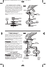
Wheel guard must be
attached when using disc
grinding or cutting wheels. Always keep wheel
guard be tween you and your work while
grinding or cutting.
The position of the guard can be adjusted to
accommodate the operation being performed.
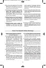
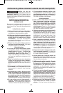
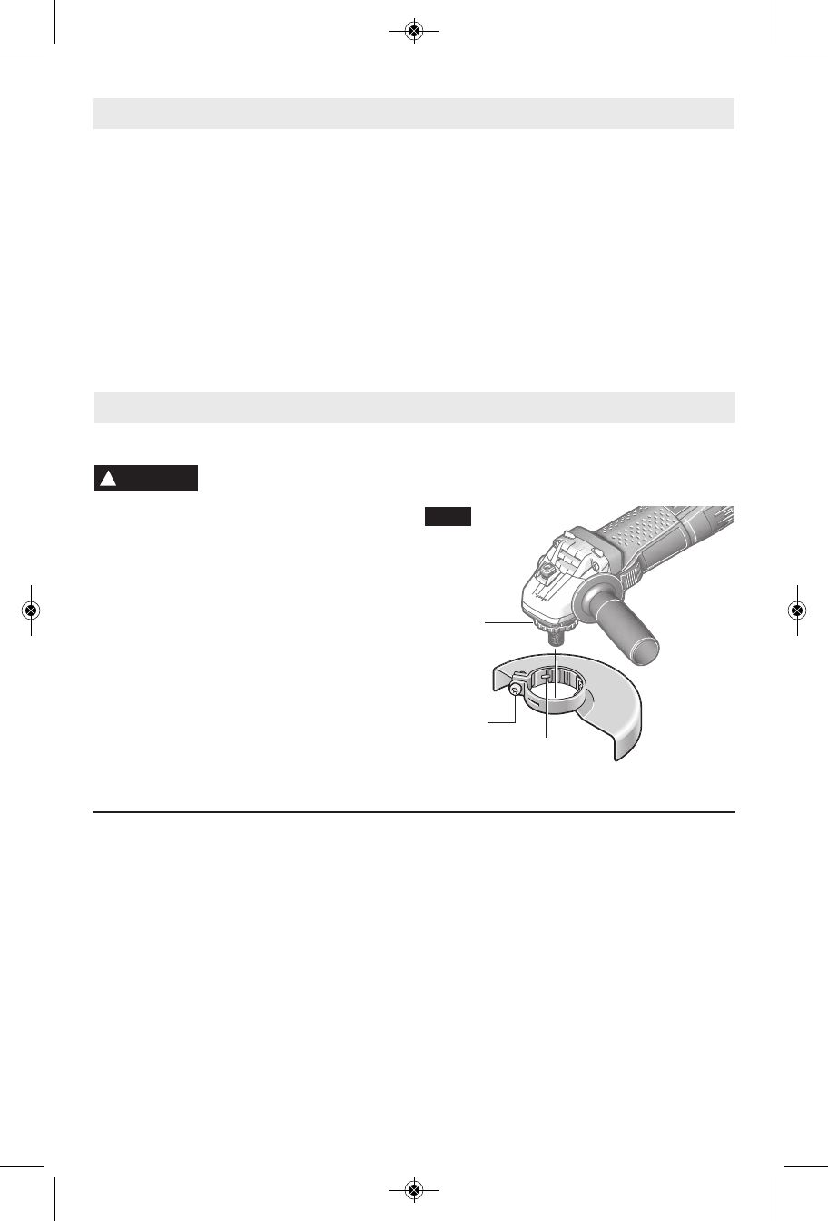
To attach wheel guard DISCONNECT tool
from power source.
Position guard on spindle neck so that the
notches on guard line up with the keys on the
spindle neck (Fig. 2).
Rotate guard either direction to desired position,
and tighten screw with the hex wrench provided
to secure guard in place.
TO REMOVE GUARD: Loosen screw with the
hex wrench provided, rotate guard until the
notches on guard line up with the keys on the
spindle neck, and lift guard off the spindle neck
(Fig. 2).
FIG. 2
::,4)3@
-10-
"!
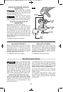
Your tool is equipped with a threaded spindle
for mounting ac ces sories. Always use the
supplied lock nut (and backing flange) that
has same thread size as spindle.
#!!
7;065(3**,::69@
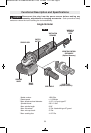
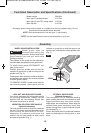
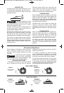
The side handle is used to control and balance
the tool. The handle must be thread ed into the
front housing on either side of the tool,
depending on per sonal preference and
comfort. Use the side handle for safe control
and ease of operation (Fig. 1).
!"
7;065(3**,::69@
The hand guard is to be used with backing
pads, sanding discs and wire brushes to keep
fingers and hand away from work surface,
sharp edges, burrs and debris. When using the
optional hand guard accessory insert side
handle through hole in guard and then thread
into housing (Fig. 1).
Ensure that hand guard is positioned between
hand and backing pad, sanding disc or wire
brush.
!
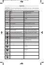
WARNING
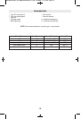
* ! For tool specifications refer to the nameplate on your tool.
Accessory speed rating must be equal to or greater than the tool’s speed rating. Do not
exceed the recommended wheel diameter.
! Not recommended for use with type 11 cup wheels.
Model number 1380 Slim
* Max. type 27 grinding wheels 4 1/2" Dia.
* Max. type 1A and 27A cutting wheel 4 1/2" Dia.
* Max. flap disc 4 1/2" Dia.
<5*;065(3,:*907;065(5+ 7,*0-0*(;065:65;05<,+
KEYS
NOTCHES
SCREW
BM 2610007691 12-09:BM 2610007691 11-09 12/18/09 11:17 AM Page 10