


!!"!!"!!
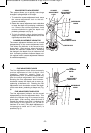
1. Remove the router sub-base.
2. The router is now ready for mounting to a
router table. Install router to mounting plate
and router table according to the instructions
provided with that accessory.
3. Attach the base to your router table using four
1/4"-20 x 1-1/2" Phillips machine screws,
washers and nuts. The length will depend on
the thickness of your router table or router
table mounting plate.
" !!!
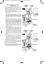
1. Install the desired bit.
2. Lift router motor to approximate desired height
and lock coarse adjust lock.
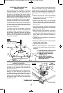
3. When used in the router table, most depth-of-
cut adjustments will be made with the fine
adjustment knob. For easier under-table height
adjustment, press the optional fine adjustment
knob extension onto the end of the fine
adjustment knob. (Fig. 25)
!!"!!"!
! $!
To prepare for use of the switch,
1. Make sure the router switch and the router
table switch are both turned off.
2. Plug the router table switch cord to wall outlet.
3. Plug the router into the "pigtail" socket on the
router table switch.
4. Lock router switch on: squeeze trigger,
depress lock-on button, and release trigger.
5. Use the router table switch to start and stop
the router.
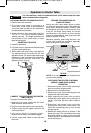
!$
"!!
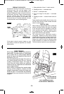
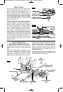
Always use your router table's fence or starter
pin and the appropriate guard and follow the
router table's instruction manual. ALWAYS feed
the workpiece from right to left across the front
of the bit. On Bosch router tables, the correct
feed direction is also shown on fence housing
and on the featherboards, when they have been
properly installed. (Fig. 26)
Whenever possible, when using the fence, use
a push stick to push the workpiece, especially
when working with narrow pieces.
!!"!!
"!"
!
1. Remove the router from the table and bring it
back to its normal upright position.
2. Remove the bit and collet chuck.
3. Remove the router table mounting plate and
reattach the router’s sub-base.
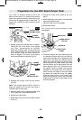
4. While supporting the router with one hand,
release the coarse adjust lock by turning it to
the left. Then lower the motor until it comes to
a rest.
5. Reactivate the plunge return spring by
pressing the router motor further down. The
router will automatically pop up from its own
spring pressure.
6. Release the depth rod from to keyhole in the
depth stop turret. (The rod needs to be moved
downward slightly in order to clear the small
circular recess on the underside of the smaller
end of the keyhole.)
-19-
7,9(;065056<;,9!()3,
69:(-,67,9(;0659,(+(5+<5+,9:;(5+;/0:96<;,94(5<(3(5+;/,96<;,9
;()3,F:4(5<(3),-69,<:05.,0;/,9
!
WARNING
FIG. 25
FIG. 26
WORKPIECE
DIRECTION
OF FEED
BIT
BEARING
TOP VIEW
!For clarity, guard and featherboard
removed from drawing.
FENCE FACE FENCE FACE
BM 2610933969 09-12_BM 2610933969 09-12.qxp 9/20/12 9:19 AM Page 19