


Assembly
-7-
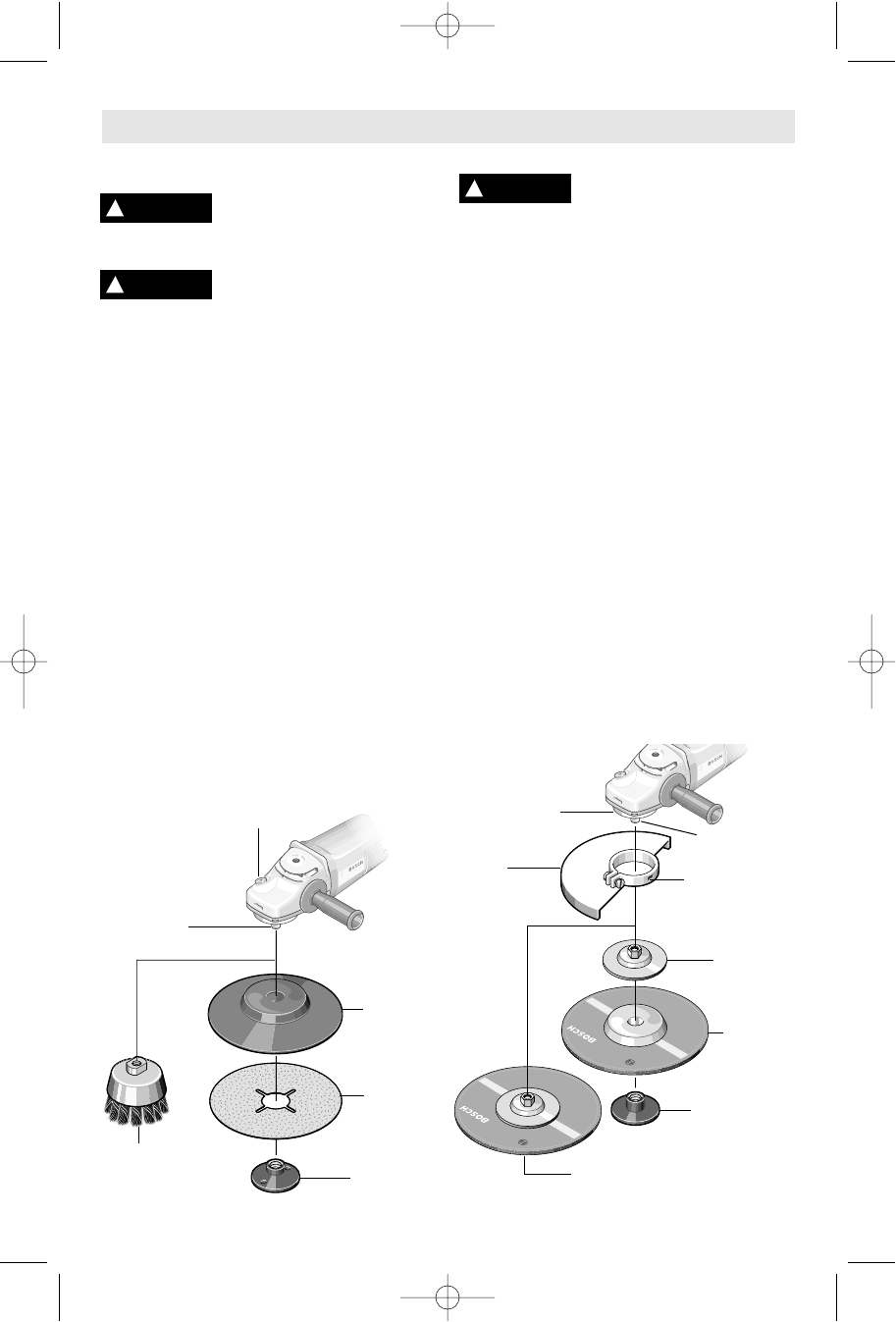
Sanding Accessories Assembly
BACKING PAD
Before attaching a backing
pad be sure its maximum
safe operating speed is not exceeded by the
nameplate speed of the tool.
Wheel guard may not be
used for most sanding
operations. Always reinstall wheel guard
when converting back to grinding
operations.
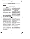
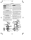
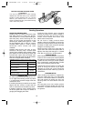
TO INSTALL BACKING PAD AND
SANDING DISC
Disconnect tool from power source. Set the
tool on its top side (spindle up). Place the
rubber backing pad onto the spindle shaft.
Center the sanding disc on top of the
backing pad. Insert the lock nut through the
disc and thread onto the spindle as far as
you can with your fingers. Press in the
spindle lock, then tighten the backing pad
securely with lock nut wrench.
TO REMOVE BACKING PAD AND
SANDING DISC
Disconnect tool from power source. Using
the lock nut wrench unscrew the nut from
the spindle, while holding spindle lock in.
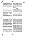
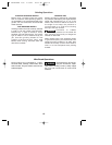
WIRE BRUSH ASSEMBLY
Before assembling wire brush to this tool,
disconnect from the power source. Wire
brushes are equipped with their own
threaded hub, simply thread on to spindle.
Be sure to seat against shoulder before
turning tool “ON”.
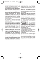
WHEEL GUARD INSTALLATION
Wheel guard must be
attached when using disc
grinding wheels. Always keep wheel guard
between you and your work while grinding.
To attach the wheel guard disconnect tool
from the power source, align wheel guard
locating tab with key way on mounting
flange and slip guard onto mounting flange.
Twist into place, always keep the wheel
guard between you and your work when
grinding. Tighten screw to secure wheel
guard.
LOCK NUT AND BACKING FLANGE
Your tool is equipped with a threaded
spindle for mounting accessories. Always
use the lock nut and backing flange that has
same thread size as spindle.
Disc Grinding Wheel Assembly
Disconnect tool from power source. Be sure
that wheel guard is in place for grinding.
When using spin-on grinding wheels, thread
directly onto the spindle.
When using mounting wheels, thread
BACKING FLANGE onto spindle, then place
GRINDING WHEEL on the spindle. Thread
on the lock nut and tighten nut using a lock
nut wrench provided with adapter kit, while
holding the spindle lock in.
TO REMOVE: Reverse procedure.
!
WARNING
!
WARNING
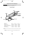
SPINDLE LOCK
RUBBER
BACKING
PAD
SANDING
DISC
LOCK NUT
SPINDLE
SPIN-ON
WIRE
BRUSH
!
WARNING
BACKING
FLANGE
LOCK NUT
WHEEL
GUARD
DISC
GRINDING
WHEEL
SPIN-ON GRINDING
WHEEL
LOCATING
TAB
SPINDLE
MOUNTING
FLANGE
BM 1609929A20 3/03 3/12/03 10:35 AM Page 7