


-16-
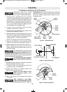
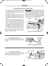
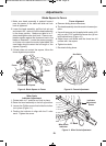
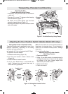
1. Make sure head assembly is pushed forward
near the center of the table and slide rail lock
knob is tightened.
2. Lower the head assembly, pull the lock pin out
and rotate it 90°, rotate to lock the head assembly
in the down position. Make sure table is in 0°
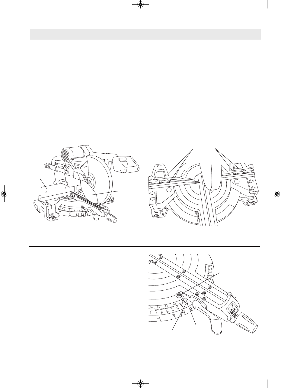
detent and tighten miter lock knob. Place a com-
bination square against the fence and next to the
blade as illustrated. Locate the square properly
so it does not contact the tooth of saw blade.The
saw blade should contact the full length of the
square (Figure 9).
3. If blade does not contact the square, follow the
fence alignment procedure.
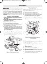
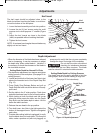
4=240;86=<4=C
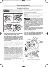
a. Remove sliding fence extensions.
b. The head assembly should remain in lowered po-
sition.
c. Use multi purpose tool (supplied with model 4410
only) or use a 7/16" socket and loosen four (4) hex
bolts behind fence (Figure 10).
d. Adjust fence until blade and the fence has full
contact with the square.
e. Tighten hex bolts.
f. Re-attach sliding fence.
39DBC<4=CB
;034(@D0A4C>4=24
86DA4;034(@D0A4C>4=24
4=24
;034
><18=0C8>=(@D0A4
4G>;CB
86DA44=2439DBC<4=C
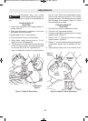
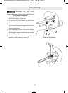
"8C4A(20;4
=3820C>A39DBC<4=C
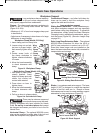
1. Rotate table to 0° position and lock in place.
2. Raise the head assembly to the full-up position.
3. Loosen the Phillips screw that holds the indica-
tor in place (Figure 11).
4. Position the indicator to align with the 0° miter
mark. Tighten the screw.
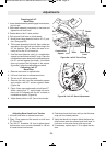
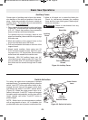
86DA4"8C4A(20;439DBC<4=C
"8C4A(20;4
=3820C>A
J"0A:
=3820C>A
39DBC<4=C
(2A4F
BM 2610012089 03-10 E:BM 2610012089 03-10 E 3/30/10 7:40 AM Page 16