


-9-
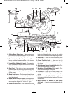
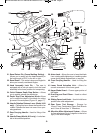
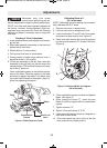
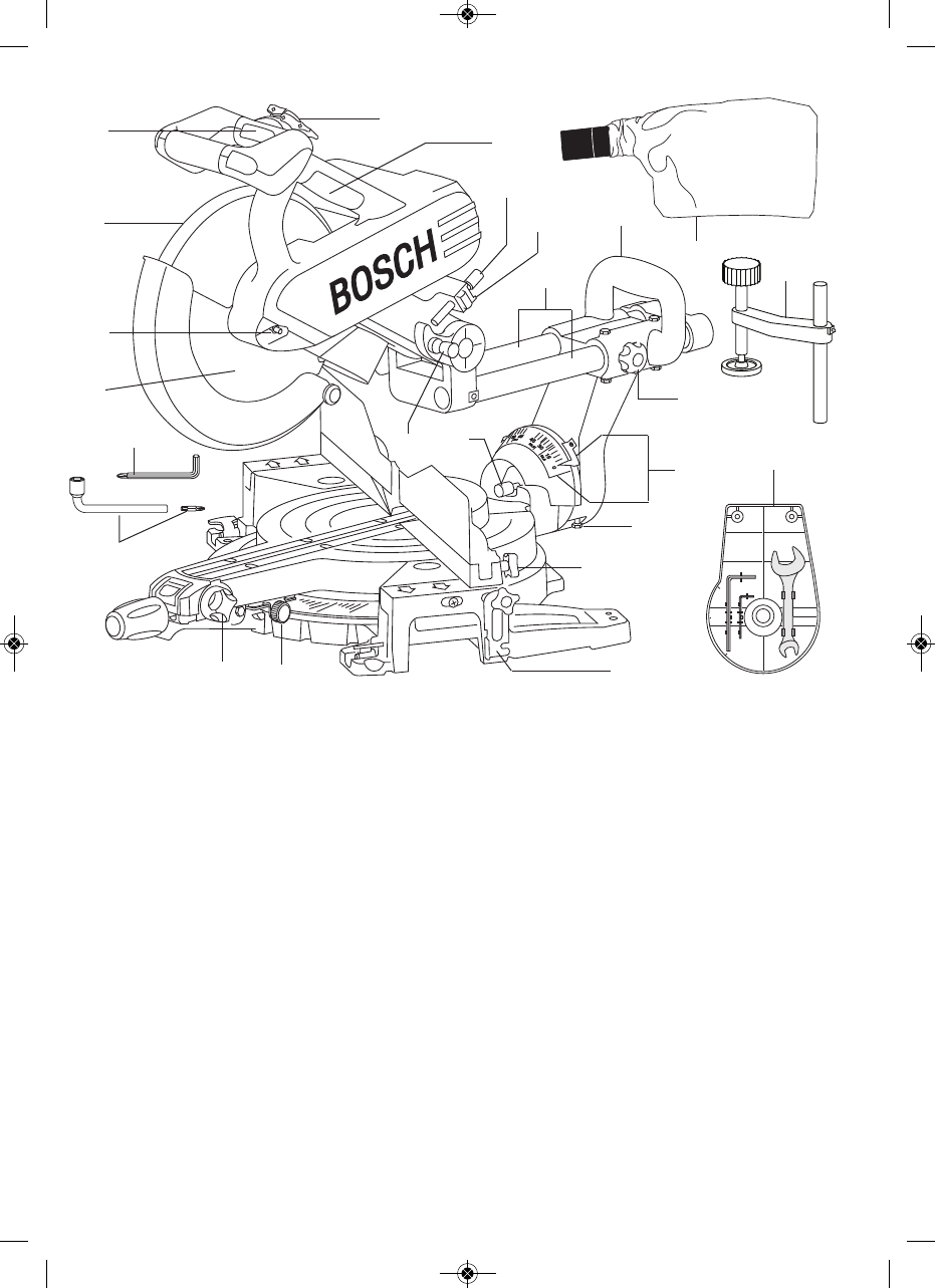
4E4;4C4=C%8=A>F=">;38=6(4CC8=6 –
Allows you to easily lock the head assembly to
the bevel angle of 33.9° to the left or right.
4E4;(20;4 – This scale is large and angled to
allow you to easily read bevel angles.
403 BB4<1;H !>2: %8= – The saw is
equipped with a lock pin used to lock the head
assembly in the lower position for transporting.
&D82:'4;40B44?C7(C>?DCC>= – Allows
you to quickly release the depth stop.
4?C7(C>? 8=439DBC<4=C =>1–Allows
you to adjust the depth of the blade for cutting
grooves in the workpiece (Figure 13, page 17).
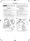
0=3;4'>C0C8>='4;40B4!4E4A">34;
>=;H – Pulling this lever allows the handle to be
rotated. Release the lever into one of four oper-
ating positions.
'40A0AAH8=60=3;4NUsed for lifting of the
tool.
0=3;4;0<?">34;>=;H NLocks han-
dle in the selected position.
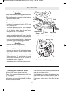
A1>A!>2:—Allows the user to keep the blade
from rotating while tightening or loosening arbor
screw during blade replacement or removal.
A>=C0AAH8=60=3;4 – Used for lifting the
tool.
!>F4A D0A3 2CD0C8>= !8=: – Allows for
smooth movement of the lower guard.
*??4A;034D0A3 – Covers upper portion of
the blade.
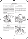
DBC060=3DBC;1>F – Used to collect
saw dust.
(;838=64=24!>2: =>1 – Used to hold fence
position after slide adjustment.
'40A >E4A )>>; (C>A064 – Storage for
10mm/17mm Combination Open End Wrench
and 1.5mm & 3mm Hex “L” Wrenches.
"82A>58=4"8C4A39DBC<4=C(HBC4< – Allows
for fine adjustment (up to 2 degrees to the left or
right) of the detent angles.
BM 2610012089 03-10 E:BM 2610012089 03-10 E 3/30/10 7:40 AM Page 9