


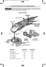
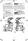
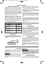
WHEEL GUARD INSTALLATION
Use wheel guard with disc
grinding wheels. Always
close the latch to secure the guard. Keep the
guard between you and the wheel. Do not
direct guard opening toward your body.
The position of the guard can be adjusted to
accommodate the operation being performed.
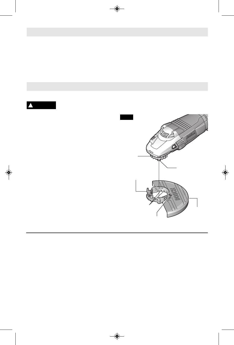
To attach wheel guard DISCONNECT tool
from power source.
Open guard release/lock latch and position
guard on spindle neck so that the notched on
guard, line up with the keys on the spindle
neck (Fig. 2).
The tightening tension of the clamp from the
protection guard can be changed by loosening
or tightening the adjustment screw. Ensure
that the protection guard is tighly seated and
check regularly.
Rotate guard either direction to desired
position, and close latch to secure guard in
place.
TO REMOVE GUARD: Open guard
release/lock latch, rotate guard until the
notches on guard line up with the keys on the
spindle neck, and lift guard off the spindle neck
(Fig. 2).
Assembly
-9-
NOTE: Always use appropriate size wheel guard.
N
OTE: For tool specifications refer to the nameplate on your tool.
NOTE: Not recommended for use with type 11 cup wheels.
!
WARNING
WHEEL
GUARD
SPINDLE
KEYS
NOTCHES
GUARD
RELEASE / LOCK
LATCH
FIG. 2
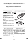
Functional Description and Specifications (Continued)
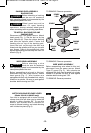
LOCK NUT AND BACKING FLANGE
Your tool is equipped with a threaded spindle
for mounting ac ces sories. Always use the
supplied lock nut (and backing flange) that
has same thread size as spindle.
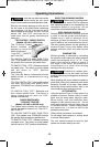
VIBRATION CONTROL SIDE HANDLE
The side handle is used to control and balance
the tool. The handle must be thread ed into the
front housing on either side of the tool,
depending on per sonal preference and
comfort. Use the side handle for safe control
and ease of operation (Fig. 1).
OPTIONAL HAND GUARD
The hand guard is to be used with backing
pads and sanding discs to keep fingers and
hand away from work surface, sharp edges,
burrs and debris. When using the optional
hand guard accessory insert side handle
through hole in guard and then thread into
housing (Fig. 1).
Ensure that hand guard is positioned between
hand and backing pad or sanding disc.
ADJUSTMENT
SCREW
BM 1609929T61 07-09:BM 1609929T61 07-09 7/8/09 1:37 PM Page 9