


-11-
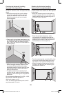
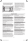
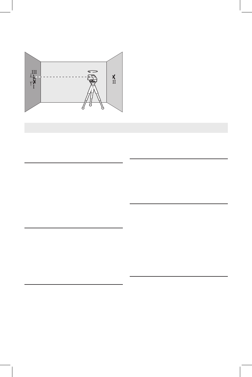
– Align the height of the measuring tool (using
the tripod or by underlaying, if required) in
such a manner that the centre point of the
laser beam is projected exactly against the
previously marked point II on wall B.
– Rotate the measuring tool by 180° without
changing the height. Allow it to level in and
mark the centre point of the laser beam on
wall A (point III). Take care that point III is as
vertical as possible above or below point I.
– The difference d of both marked points I and
III on wall A results in the actual height
deviation of the measuring tool alongside the
Longitudinal axis.
On the measuring distance of 2 x 65ft =130ft,
the maximum allowable deviation is:
130 ft x ±0.3 mm/m = ±1/2".
Thus, the difference d between points I and III
may not exceed 1/2"(max.).
For marking, always use only the centre
of the laser point or the laser line. The size
of the laser point as well as the width of the
laser line change with distance.
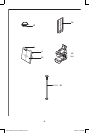
Working with the Tripod (Accessory)
A tripod offers a stable, height-adjustable
measuring support. Position the measuring tool
with the 1/4” tripod mount 7 onto the thread
of the tripod 16 or a commercially available
camera tripod. For fastening to a commercially
available construction tripod, use the 5/8” tripod
mount 6. Tighten the measuring tool with the
tripod mounting stud.
Adjust the tripod roughly before switching on the
measuring tool.
Fastening with the Universal Holder
(Accessory)
With the universal holder 15, you can fasten the
measuring tool, e.g., to vertical surfaces, pipes
or magnetizable materials. The universal holder
is also suitable for use as a ground tripod and
makes the height adjustment of the measuring
tool easier.
Adjust the universal holder 15 roughly before
switching on the measuring tool.
Working with the Measuring Plate
(Accessory) (see figures A–B)
With the measuring plate 14, it is possible to
project the laser mark onto the floor or the laser
height onto a wall.
With the zero field and the scale, the offset or
drop to the required height can be measured
and projected at another location. This
eliminates the necessity of precisely adjusting
the measuring tool to the height to be projected.
The measuring plate 14 has a reflective coating
that enhances the visibility of the laser beam
at greater distances or in intense sunlight. The
brightness intensification can be seen only
when viewing, parallel to the laser beam, onto
the measuring plate.
Working with the Laser Target Plate
The laser target plate 13 increases the
visibility of the laser beam under unfavourable
conditions and at large distances. The reflective
part of the laser target plate 13 improves
the visibility of the laser line. Thanks to the
transparent part, the laser line is also visible
from the back side of the laser target plate.
Laser Viewing Glasses (Accessory)
The laser viewing glasses filter out the ambient
light. This makes the red light of the laser
appear brighter for the eyes.
Do not use the laser viewing glasses as
safety goggles. The laser viewing glasses
are used for improved visualisation of the laser
beam, but they do not protect against laser
radiation.
Do not use the laser viewing glasses as
sun glasses or in traffic. The laser viewing
glasses do not afford complete UV protection
and reduce colour perception.
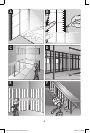
Work Examples (see figures C – F)
Applicational examples for the measuring tool
can be found on the graphics pages.
Always position the measuring tool close to the
surface or edge subject to checking, and allow it
to level in prior to each measurement.
Always measure the distances between laser
beam or laser line and a surface or edge at two
points as far as possible away from each other
(e.g. with the measurement plate
14).
d
180°
A
B
Working Advice
GCL 25 Manual with translations.indd 11 4/24/12 8:29 AM