


-9-
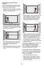
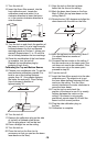
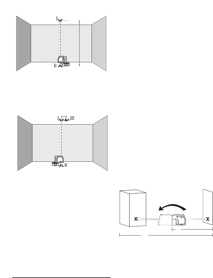
– Position the tool in such a manner that the
upper plumb beam points against the line
on the ceiling. Allow the tool to level in.
Mark the center of the upper laser point on
the line on the ceiling (point I). Also, mark
the center of the laser point on the floor
(point II).
– Rotate the tool by 180°. Position it in such
a manner that the center of the bottom
laser point is directed on the already
marked point II and the upper laser point is
directed against the line on the ceiling.
Allow the tool to level in. Mark the center
of the upper laser point on the line on the
ceiling (point III).
– The difference d of both marked points I
and III on the ceiling results in the actual
deviation of the tool to the plumb line.
On the measuring distance of 2 x 13 ft = 26 ft
, the maximum allowable deviation is:
26 ft x ±0.0036 in/ft = ±3/16 in.
Thus, the difference d between points I and
III should not exceed 3/16 in (max.).
Recalibration Procedure (Front, Up &
Down Beams)
All tools are calibrated when processed
through the Bosch quality control program.
This process assures that the customer
receives a superior product which conforms
to the Product Specifications. Although tools
have been calibrated before reaching our
customers, it contains many precision
machined parts which may be affected if the
instrument is subjected to abuse. Therefore,
if the device is ever dropped or sustains
significant impact, the user should check
calibration by following these steps:
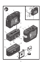
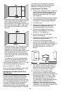
Calibrating the Front Beam
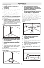
1. Choose your recalibration site. To get the
most accurate calibration possible, it is
best to use two vertical (plumb) surfaces
directly opposite each other 100’ apart
(50’ minimum).
2. The recalibration process should be done
on level ground so that the height of the
tool does not change during calibration.
3. Turn the tool off.
4. Remove the calibration plug on the front
of tool with a flathead screw-driver.
Set the plug where it will not be lost.
5. Place the tool about 5’ from one of
the two vertical surfaces. This will be
Surface 1. Turn the tool on.
6. Ensure the tool is level (the laser
beam is not blinking).
7. Position the front beam on Surface 1 and
mark the dot location Mark A.
8. Turn the tool 180 degrees (make
sure you do not change the height) so
that the front laser beam is now visible on
the opposing surface, Surface 2. Mark
the laser dot position on Surface 2,
Mark B.
9. Move the tool to about 5’ from Surface 2
(the location you just marked). Raise or
lower the tool so that the laser dot hits
the spot you have already marked.
10. Turn the tool 180 degrees (make
sure you do not change the height) so
that the front laser beam is now visible on
the opposing surface, Surface 1. Mark
this new spot, Mark C. You should now
have two spots marked on Surface 1.
Any difference in height between the two
marks is equal to twice the error in
calibration. If the two marks are at the
same point, the unit does not need to be
calibrated. If the two marks are not on the
same point, proceed to step 11.
13 ft
B
A
5
ʹ
50
ʹ
1 ecafruS2 ecafruS
d