


-10-
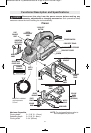
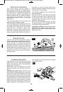
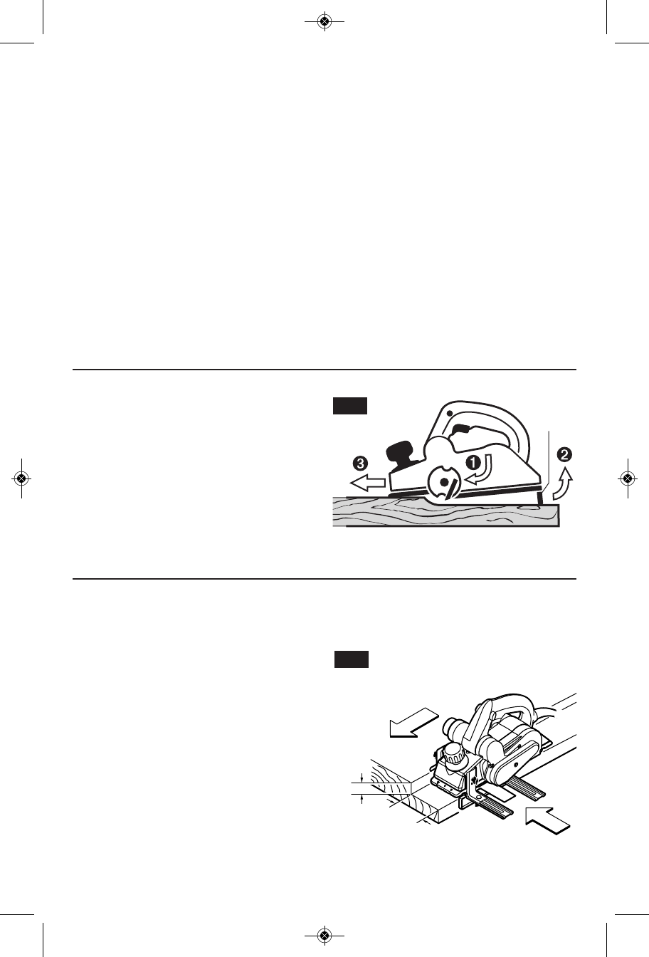
The cutting depth (planing depth) is
determined by the difference in height between
the adjustable front shoe and the fixed rear
shoe of the planer. The depth knob adjusts the
front shoe, which retracts and exposes the
blade and determines the amount of material
removed from the workpiece. The cutting
depth range is from 0 to 1/16" (1.5 mm) per
pass. (Fig. 1)
The appropriate depth of cut and feed rate
depends on the workpiece material:
To avoid clogging and/or damage to the motor,
a more (thin) cut and/or a slower feed rate may
be needed if the material has any of these
characteristics: hardness; gumminess,
sappiness, moisture, paint, varnish and/or
knots. Also, when planing against the grain or
across the grain rather than with the grain, a
shallower cut and/or slower feed rate is
required. Whenever possible, test by planing a
similar piece of scrap material.
Use multiple, progressive cuts to achieve the
total desired depth.
Start with a thin cut. If the plane moves freely
through the workpiece with no excessive load
on the motor, the depth setting can be
increased before the next cut. (Do not change
depth of cut while planing.)
When near the desired total depth, re-adjust
the planing depth to a thin setting for the final
cut to obtain a good surface finish.
(.978-2+8,))48,3*98 Rotate depth
adjustment knob clockwise until the indicator is
aligned with the desired cutting depth on the
depth scale (Fig. 1).
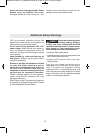
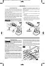
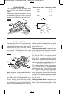
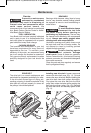
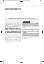
The park rest stand automatically springs
down to help keep the blade from coming in
contact with the work surface when planer is
not in use (Fig. 7). The park rest stand is
designed to swing up and out of the way by it
itself when the back of the plane crosses the
leading edge of the workpiece (Fig. 6). It will
also swing up when planing begins in the
middle of the work piece (in from the edge of
the work piece).
FIG. 7
PARK
REST
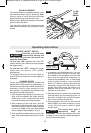
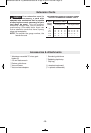
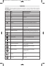
The guide fence can be used to control the
width of the cut or for simply providing added
stability and protection when cutting materials
that are up to 3-1/4" wide.
38) When used for rabbeting, the fence
must be attached to the left side of the tool.
(Fig. 1).
278%00-2+8,)+9-()*)2') Place the wing
knob through the appropriate hole in the guide
bracket and screw into preferred side of the
housing. Securely tighten wing knob. Setting
the cutting width: Place wing knob through the
appropriate fence arm and slide along the
guide bracket to the desired position. Securely
tighten wing knob. Be certain that the flat
washer (supplied) is fitted between the bottom
of the guide fence and wing knob or the guide
fence is likely to slip.
82 mm
max
9 mm
max
FIG. 8
BM 2610021505 02-12_BM 2610021505 02-12.qxp 9/18/12 2:56 PM Page 10