


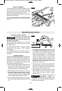
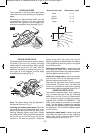
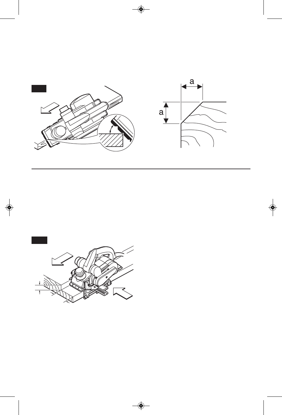
The V-grooves in the front planer base plate
allow quick and easy beveling of workpiece
edges.
Depending on required bevel width, use the
corresponding V-groove. For this, place the
planer with the V-groove onto the edge of the
workpiece and guide it along the edge (Fig. 9).
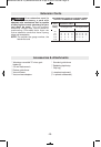
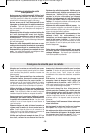
633:)83&)97)( -1)27-32%11
None 0 – 4
Small 2 – 6
Medium 4 – 9
Large 6 – 10
-11-
45°
"
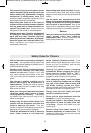
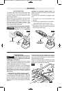
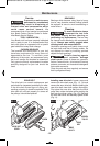
The deluxe guide fence can be used to control
the width of the cut or for simply providing
added stability and protection when cutting
materials that are up to 3-1/4" wide, with the
additional capability of guiding the planer on
any angle up to 45 degrees, to allow edge
chamfering and beveling (Fig. 9).
38) The deluxe fence must be attached to
the left side of the tool. (Fig. 1).
278%00-2+8,)()09<)+9-()*)2') Place the
wing knob through the appropriate hole in the
guide bracket and screw into left side of the
housing. Securely tighten wing knob. Setting
the cutting width: Place wing knob through the
left fence arm and slide along the guide
bracket to the desired position. Securely
tighten wing knob. Be certain that the flat
washer (supplied) is fitted between the bottom
of the guide fence and wing knob or the guide
fence is likely to slip.
)88-2+8,)'988-2+;-(8, Loosen wing knob
and using the width scale, slide the fence
along the guide bracket to the desired position.
Securely tighten wing knob (Fig. 1).
)88-2+8,)'988-2+%2+0) Loosen round knobs
and pivot the fence to the desired position.
Securely tighten round knobs (Fig. 1).
Note that the adjustable front shoe contains
three chamfer V-grooves, which will follow the
corner of a workpiece to allow easier handling
when using the deluxe angle/width fence (Fig. 9).
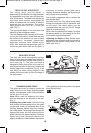
The optional rabbeting depth stop accessory
(Fig. 1) allows the user to set any rabbeting
depth from 0 to 5/16" (9 mm). For best results,
it is important that the blade be properly
aligned (See "BLADE ALIGNMENT"). The
width of the rabbet is controlled by the width
fence. The final depth is achieved by repetitive
cutting until the rabbeting depth guide contacts
the workpiece. The maximum rabbeting depth
is 5/16" (9 mm).
)88-2+8,)6%&&)8()48, Loosen wing knob
and using the depth scale on the rabbeting
depth stop, set the desired rabbet depth.
Securely tighten wing knob (Fig. 1).
FIG. 9
82 mm
max
9 mm
max
FIG. 10
BM 2610021505 02-12_BM 2610021505 02-12.qxp 9/18/12 2:56 PM Page 11