


-9-
Operating Instructions
Assembly
D
isconnect battery pack
from tool or place the switch
in the locked or off position before making
any assembly, adjustments or changing
accessories
. Such preventive safety measures
reduce the risk of starting the tool accidentally.
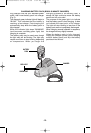
INSTALLING AND REMOVING
ACCESSORIES
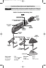
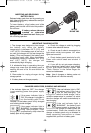
1. To install accessories, align holes in
accessory with locating pins on accessory
holder in desired position. Assure that pin in
holder are engaged into holes in accessory
and securely tighten with with hex bolt
provided (Fig. 1).
Your accessories can be engaged into
accessory holder 12 positions 30 degrees
apart.
For intermediate position an adapter is
provided that will allow you to attach the
accessory in any position. Use of adapter will
a
lso allow you to use most competitor
accessories.
2. To remove accessory, loosen and remove
hex bolt and remove accessory from holder
(Fig. 1).
INSTALLING SANDING SHEETS
Your tool uses hook-and-loop backed
sandpaper, which firmly grips the backing pad
when applied with moderate pressure.
To change, merely peel off the old sandpaper,
remove dust from the backing pad if
necessary, and press the new sandpaper in
place (Fig. 1).
After considerable use the backing pad
surface will become worn, and the backing pad
must be replaced when it no longer offers a
firm grip. If you are experiencing premature
wear of the backing pad facing, decrease the
amount of pressure you are applying during
operation of the tool.
SLIDE "ON/OFF" SWITCH
The tool is switched "ON" by the slide switch
located on the topside of the motor housing
(Fig. 1).
TO TURN THE TOOL "ON" slide the switch
button forward to the “I” .
TO TURN THE TOOL "OFF" slide the switch
button backward the “0” .
Hold the tool with both hands
while starting the tool, since
torque from the motor can cause the tool to
twist.
VARIABLE SPEED DIAL
This tool is equipped with a variable speed
dial. The speed may be controlled during
operation by presetting the dial in any one of
six positions (Fig. 1).
BATTERY CHARGE CONDITION
INDICATOR LIGHTS
Your tool is equipped with charge condition
indicator lights (Fig. 1). The indicator lights
shows the charge condition of the battery
during operation.
For safety reasons, only check the charge
condition when the tool is at a complete
standstill.
To check the charge condition, press and hold
the charge condition indicator button with the
tool in the off position.
!
WARNING
!
WARNING
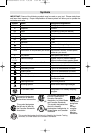
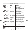
LED Capacity
Continuous lighting 3 x green
2/3
Continuous lighting 2 x green 1/3
Continuous lighting 1 x green
1/3
Flashing light 1 x green reserve
APPLICATION
Your tool is intended for sawing and separating
wooden materials, plastic, plaster, non-ferrous
metals and fasteners (e.g. nails and clamps)
as well as for working on soft wall tiles and for
dry sanding and scraping of small surfaces. It
is especially suitable for working close to
edges and for flush cutting.
BM 2609140575 07-08 7/8/08 3:54 PM Page 9