


4
Operation (Continued)
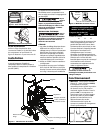
• Exhaust Tube - This tube carries
compressed air from the pump to the
check valve. This tube becomes very
hot during use. To avoid the risk of
severe burns, never touch the
exhaust tube.
• Check Valve - A one-way valve that
allows air to enter the tank, but
prevents air in the tank from flowing
back into the compressor pump.
• Handle - Designed to move the
compressor.
• Drain Valve - This valve is located
on the bottom of the tank. Use this
valve to drain moisture from the
tank daily to reduce the risk of
corrosion.
Reduce tank pressure below 10 psi,
then drain moisture from tank daily to
avoid tank corrosion. Drain moisture
from tank by opening the drain valve
located underneath the tank.
BEFORE EACH START-UP
OPERATING PROCEDURE
1. Turn regulator knob fully counter
clockwise (to the left) to close air
flow.
2. Connect air hose to outlet of
regulator.
3. Turn on/off switch to OFF position.
4. Plug in power cord.
5. Turn on/off switch to AUTO position
and let compressor run until it
reaches automatic shutoff pressure.
6. Attach tire chuck or tool to end of
hose.
7. Turn regulator knob clockwise (to
the right) to desired pressure of tool
being used.
On/Off cycling of compressor
In the AUTO position, the compressor
pumps air into the tank. When a shut-
off (preset “cut-out”) pressure is
reached, the compressor automatically
shuts off.
If the compressor is left in the AUTO
position and air is depleted from the
tank by use of a tire chuck, tool, etc., the
compressor will restart automatically at
its preset “cut-in” pressure. When a tool
is being used continuously, the
compressor will cycle on and off
automatically.
In the OFF position, the pressure switch
cannot function and the compressor
will not operate. Make sure switch is in
OFF position when connecting or
disconnecting power cord from
electrical outlet.
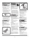
CONNECTING / DISCONNECTING
PORTABLE COMPRESSOR
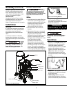
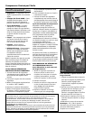
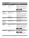
Unhooking the Small Tank from
the Large Tank
1. Remove the connection hose by
pulling back the collar on the
coupler (this is not a normal
pneumatic coupler, no air will be
discharged from the coupler or the
fitting).
2. Unscrew the knob
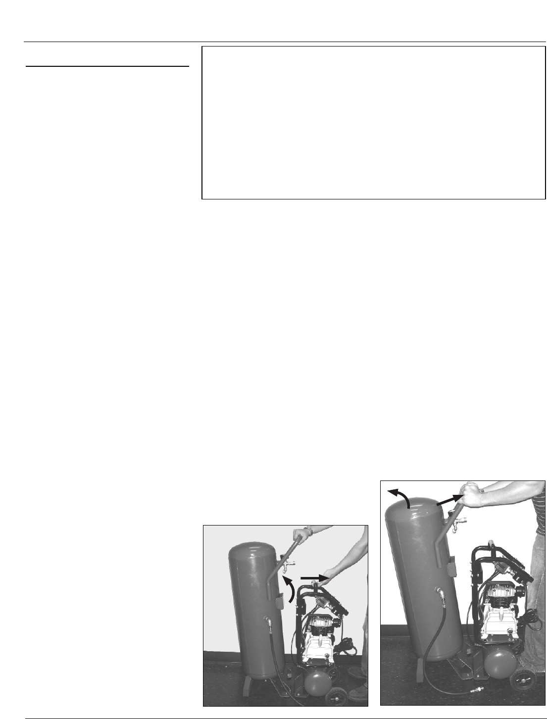
3. Lean back the Large Tank and pull
the Small Tank forward to unhook
the bottom of the two tanks (See
Figure 6).
4. Replace knob into large tank for
storage.
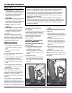
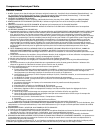
Connecting the Small Tank to the
Large Tank
1. Align the feet of the two tanks so
that the Small Tank foot bracket fits
into the Large Tank’s foot bracket
opening.
2. Lean back and slide forward the
Large Tank so that the mounting
pins on the Large Tank engage into
the holes on the Small Tank (See
Figure 7).
3. Reconnect the knob to secure the
Large Tank with the handle of the
Small Tank.
4. Reconnect the connection hose.
Note: If air pressure is in either tank it
may be difficult to push coupler onto
the fitting.
MOISTURE IN COMPRESSED AIR
Moisture in compressed air will form into droplets as it comes from an air
compressor pump. When humidity is high or when a compressor is in
continuous use for an extended period of time, this moisture will collect in
the tank. When using a paint spray or sandblast gun, this water will be
carried from the tank through the hose, and out of the gun as droplets
mixed with the spray material.
IMPORTANT: This condensation will cause water spots in a paint job,
especially when spraying other than water based paints. If sandblasting, it
will cause the sand to cake and clog the gun, rendering it ineffective. A filter
in the air line (MP3105), located as near to the gun as possible, will help
eliminate this moisture.
www.chpower.com
Oil-Lubricated Compressors
Figure 6
Figure 7