11
Airless Paint Systems
Operating Instructions and Parts Manual
www.chpower.com
halves and remove both coupling
halves. This will disconnect piston
rod from connecting rod and
gearbox assembly.
3. Screw the suction nut off the pump
and remove inlet valve assembly.
4. Using the rod collar tool, loosen
the packing nut (CCW) and push
the piston down and out of the
fluid body.
5. Place piston holder in a vise. Slide
the piston into the holder and lock
in place with a 1/4" pin.
6. Clean all parts and inspect them
carefully for wear or damage.
Inspect the outside of the piston
rod for scoring or wear. Replace
these parts if needed. A worn
piston rod will cause premature
wear of packings.
7. Using a 3/8" allen wrench to
unscrew the outlet seat support
from the piston.
8. Remove the outlet seat, O-ring,
outlet ball and ball cage.
9. Inspect the outlet ball and seat for
wear. Replace as required.
NOTE: Inlet seat is reversible.
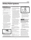
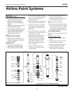
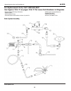
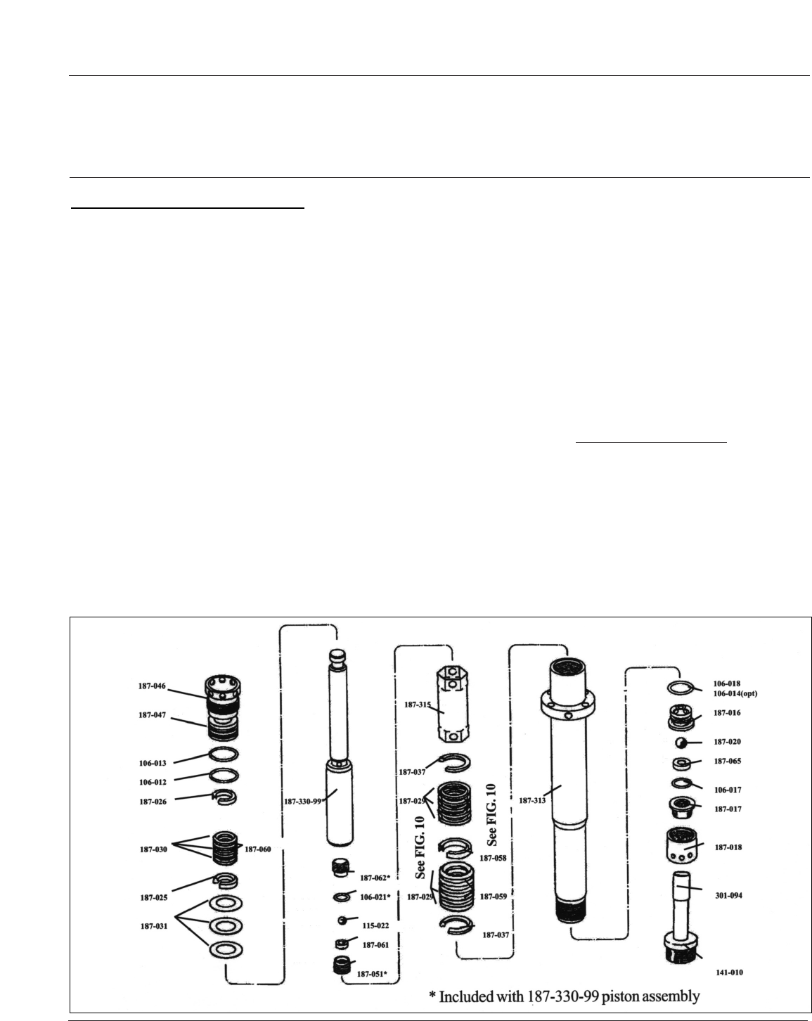
10. Install parts back into piston rod as
shown in Figure 11.Place two drops
of loctite No. 242 (blue) on threads
of the outlet seat support before
assembling and torque to 20 ft-lbs.
CLUTCH REPLACEMENT
NOTE: See clutch assembly parts list on
page 26.
Remove clutch as follows:
1. Remove upper and lower clutch
covers.
2. Remove splash cover from clutch
brackets and spacer tubes.
3. Disconnect two clutch leads from
electrical control board leads.
4. Remove gearbox cover with
manifold filter from gearbox.
AL2810
Service
(Cont.)
INLET VALVE
1. Using the rod collar tool, screw
suction nut off of fluid body.
(Suction nut contains intake seat
support.)
2. Remove inlet seat, O-ring, inlet ball
and ball cage with O-ring.
3. Clean all parts and inspect them for
wear or damage. Replace parts as
needed. Old O-rings should be
replaced with new ones.
NOTE: Inlet seat is reversible.
4. Clean inside of fluid body.
5. Reassemble the valve and screw it
onto the fluid body if no further
service is needed.
OUTLET VALVE
1. Stop piston rod in middle of its
stroke. Remove retaining rings.
2. Slip the sleeve off the coupling
Figure 11 - Piston Assembly


