


Nota: se deberán usar únicamente
las máscaras para polvo aptas para
trabajar con polvo y humos de pintura
de plomo. Las máscaras para pintura
normales no proporcionan esta
protección. Consulte al proveedor de
su ferretería local para que le indique
la máscara (aprobada por NIOSH)
adecuada.
3. NO deberá COMER, BEBER ni
FUMAR en el área de trabajo para
evitar ingerir partículas de pintura
contaminadas. Los trabajadores
deberán lavarse y limpiarse ANTES
de comer, beber o fumar. Los
artículos de comida, bebida o para
fumar no deberán dejarse en el área
de trabajo donde el polvo pueda
asentarse.
B. SEGURIDAD AMBIENTAL
1. La pintura se deberá quitar de un
modo que minimice la cantidad de
polvo que se genere.
2. Las áreas donde se esté quitando
la pintura deben sellarse con
coberturas plásticas de 4 mils de
grosor.
3. El lijado se debe realizar de un
modo que reduzca el traslado del
polvo de pintura fuera del área de
trabajo.
C. LIMPIEZA Y DESECHO
1. Todas las superficies del área de
trabajo deben aspirarse y limpiarse
por completo a diario durante el
proyecto de lijado. Las bolsas de
filtro de la aspiradora deben
cambiarse con frecuencia.
2. Los paños cobertores de plástico
deben juntarse y desecharse con
todos los restos de polvo y demás
residuos. Deben colocarse en
receptáculos sellados para basura
y desecharse mediante los
procedimientos de recolección
de basura normales. Durante la
limpieza, los niños y las mujeres
embarazadas deben mantenerse
alejados del área inmediata de
trabajo.
3. Todos los juguetes, muebles
lavables y utensilios que usen los
niños deben lavarse muy bien antes
de volver a usarlos.
Ensamblaje
INSTALACIÓN DEL MANGO
LATERAL
1. DESENCHUFE LA RECTIFICADORA.
2. INSTALE EL MANGO LATERAL
ATORNILLÁNDOLO AL COSTADO
DE LA CAJA DE ENGRANAJES.
Nota: el mango se puede instalar
del lado derecho o izquierdo de la
rectificadora, según la preferencia del
operador. EL MANGO LATERAL DEBE
USARSE SIEMPRE PARA EVITAR LA
PÉRDIDA DE CONTROL Y POSIBLES
LESIONES GRAVES.
3. Ajuste el mango lateral de modo
seguro.
INSTALACIÓN DE LA RUEDA
ABRASIVA
Se proporciona una protección para
la rueda con la herramienta.
Utilice siempre una protección
aprobada y correctamente ajustada
para la rueda cuando use esta
herramienta.
1. DESENCHUFE LA RECTIFICADORA.
2. Coloque la herramienta dada
vuelta con el vástago hacia arriba.
3. Coloque la protección en el reborde
de montaje. Gire la protección
hasta una posición que ubique la
protección entre el operador y la
rueda abrasiva. Ajuste el tornillo
de fijación para asegurar
la protección en la posición
correcta.
Asegúrese siempre de que la protección
de la rueda esté entre el operador y la
rueda, de modo que las lascas o trozos
de rueda que se puedan desprender
sean desviados lejos del operador.
!
ADVERTENCIA
!
ADVERTENCIA
INSTALACIÓN DE LAS RUEDAS
ACCESORIAS
1. DESENCHUFE LA RECTIFICADORA.
No desenchufar la rectificadora puede
hacer que se encienda accidentalmente
causando lesiones graves.
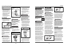
2. Su rectificadora se envía con el
reborde del disco y la tuerca de
sujeción conectados al vástago
(ver Figuras 2 y 3).
3. Presione el botón de bloqueo del
vástago y gire la tuerca de sujeción
hasta que se bloquee el vástago.
Para evitar dañar el vástago o el
bloqueo del vástago, siempre deje
que el motor se detenga por
completo antes de enganchar el
bloqueo del vástago.
4. Afloje y quite la tuerca de sujeción
del vástago. NO quite el reborde del
disco.
!
ADVERTENCIA
17 Sp
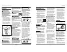
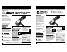
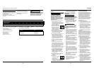
Figura 1
Tuerca de sujeción
enroscada de modo
incorrecto
Cepillo
circular de
alambre
Tuerca de
sujeción
enroscada
de modo
correcto
Rueda
abrasiva
Reborde
del disco
Tuerca
de
sujeción
Vástago
Llave
Para
ajustar
Para
aflojar
Protección
Figura 2
Figura 3
DG470500CK
Assembly (Cont’d.)
operator and the grinding wheel.
Tighten clamp screw to secure the
guard in proper position.
Always make sure
the wheel guard is positioned between
operator and the wheel, so that flying
chips or pieces of a wheel that might
break will be deflected away from the
operator.
INSTALLING ACCESSORY WHEELS
1. UNPLUG YOUR GRINDER.
Failure to unplug
your grinder could result in accidental
starting causing serious injury.
2. Your grinder is shipped with the
disc flange and clamp nut attached
to the spindle (see Figures 2 & 3) .
3. Depress spindle lock button and
rotate clamp nut until spindle locks.
To prevent damage to the spindle
or spindle lock, always allow motor
to come to a complete stop before
engaging spindle lock.
!
WARNING
!
WARNING
4. Loosen and remove clamp nut from
spindle. DO NOT remove disc
flange.
5. Place the accessory wheel over the
spindle.
Always install
grinding wheel and abrasive mop disc
with the depressed center against the
disc flange as shown above. Failure to
do so will cause the grinding wheel to
crack when tightening the clamp nut.
This could result in serious personal
injury because of loose particles
breaking off and being thrown from
the grinder. Do not overtighten.
6. To install grinding wheel and wire
wheel brush: Thread the clamp nut
on the spindle with the flat side of
nut facing up. Fit raised, small
diameter portion of the clamp nut
into the hole in the wheel and
finger tighten.
7. To install abrasive mop disc: Thread
the clamp nut on the spindle with
the flat side of nut facing down.
Finger tighten (see Figure 4).
8. Depress the spindle lock button and
rotate the wheel clockwise until the
spindle locks in position.
9. Securely tighten the clamp nut with
the wrench provided. Do not
overtighten.
Wire wheel brush
bristles will bend during use and show
their direction of rotation. When
reusing the wire wheel brush, always
mount it to rotate in the same direction
as in prior use. Failure to heed this
warning can result in bristle breaking
and extreme vibration of the wire
wheel brush that could result in serious
personal injury.
!
WARNING
!
WARNING
Operation
Safety
glasses must be worn
during operation.
Make sure work is
held securely in vise or clamped in
place prior to starting operation. Loose
work may spin and cause bodily injury.
Be certain wheel guard and auxiliary
handle are installed. Firmly grip the
auxiliary handle and motor housing.
Lift up rear of motor housing so that
only the front section of grinding
wheel contacts the work. Use light
pressure. Always lift the grinder off
work before starting or stopping
motor. The arrow on the front gear
housing indicates the direction in
which the grinding wheel rotates.
GRINDING, SANDING, BRUSHING
Always carefully select and use
grinding wheels that are
recommended for the material to be
ground. Make sure that the minimum
operating speed of any accessory
wheel selected is not less than 11,000
RPM.
The grinding wheel provided with your
grinder is suitable for grinding welds,
preparing surfaces to be welded,
grinding structural steel, and grinding
stainless steel. The wire wheel brush is
suitable for removing paint or rust
from metal surfaces. The abrasive mop
disc is suitable for sanding flat metal or
wood surfaces.
Never use your
grinder with the guard removed. This
tool has been designed for use ONLY
with the guard installed. Attempting to
use grinder with guard removed will
result in loose particles being thrown
against the operator resulting in
serious personal injury.
Inspect wire wheel
brush before each use. Never use one
that is rusted, damaged or not marked
for a minimum speed of 11,000 RPM or
higher. Failure to heed this warning
can result in serious personal injury.
The key to efficient operation begins
by controlling the pressure and surface
contact between the grinding wheel
and workpiece. Flat surfaces are
ground at an acute angle, normally
between 5 to 15 degrees (see Figure 5).
!
WARNING
!
DANGER
!
CAUTION
!
WARNING
4
www.chpower.com
Operating Instructions and Parts Manual
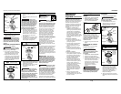
Clamp nut
turned incorrectly
Abrasive
mop disc
Clamp nut
turned
correctly
Clamp nut
turned incorrectly
Wire
wheel
Clamp nut
turned
correctly
Grinding
wheel
Disc
Flange
Clamp
Nut
Spindle
Wrench
To
Tighten
To
Loosen
Guard
Figure 2
Figure 3
Figure 4
Informaciones
Generales de
Seguridad (Continuación)