


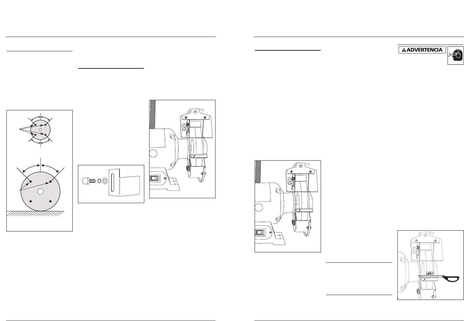
Ensamblaje
(Continuación)
incluidos, las arandelas de seguridad y
las arandelas planas. Deben usarse dos
de cada una para asegurar cada apoyo
para la pieza de trabajo.
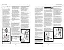
Nota: El apoyo para la pieza de trabajo
que tiene la ranura para la broca
impresa en ángulo en el mismo debe
usarse para el montaje para la mano
izquierda.
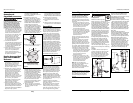
El borde interior del apoyo debe
quedar posicionado en forma que la
distancia del diámetro externo de la
rueda abrasiva sea menor que el grueso
del material a rectificar, pero no más
de 1/8 pulg.[3 mm]. Una vez fijada esta
distancia, apriete firmemente ambos
pernos de retención. Una vez
terminado el montaje, gire la rueda a
mano para asegurarse de que ninguna
de las partes ensambladas entre en
contacto con la rueda. El ensamble
terminado debe parecerse al que se
ilustra en la Figura 6.
Repita el proceso para ensamblar en el
lado izquierdo de la rectificadora las
demás piezas adjuntas que quedan.
Montaje
Si la rectificadora de banco tiene la
tendencia a volcarse, resbalar o
desplazarse sobre la superficie de
apoyo, entonces es necesario sujetarla
firmemente. Para ese fin, primero
asegúrese de que la rectificadora esté
desconectada del suministro de
corriente. Luego sujete la rectificadora
de banco por medio de los orificios de
montaje ubicados en la base de la
rectificadora y unos tornillo (no
incluidos).
Cambio de las ruedas
abrasivas
Para cambiar la rueda abrasiva, primero
desconecte la rectificadora del
suministro de corriente. Retire los tres
tonillos que sujetan la protección
externa de la rueda abrasiva.
• Para retirar la tuerca de retención en
el lado derecho de la rectificadora,
agarre firmemente con una mano la
rueda abrasiva en el lado izquierdo
de la rectificadora y gire la turca de
retención en sentido antihorario.
• Para retirar la tuerca de retención en
el lado izquierdo de la rectificadora,
agarre firmemente con una mano la
rueda abrasiva en el lado derecho de
la rectificadora y gire la turca de
retención en sentido horario.
Es posible que el usuario deba golpear
el mango de la llave con un martillo de
cabeza blanda para aflojar la tuerca.
Retire la tuerca de retención y, después
de notar su orientación, retire la
arandela grande y abombada, y el
empaque de papel debajo de la misma.
Retire la rueda moledora vieja y
coloque la nueva en su lugar. Coloque
el empaque de papel y luego la
arandela grande con la misma
orientación que tenía cuando la quitó.
• Para asegurar la tuerca de retención
en el lado derecho de la
rectificadora, agarre firmemente con
una mano la rueda abrasiva en el
lado izquierdo de la rectificadora y
gire la turca de retención en sentido
horario.
• Para asegurar la tuerca de retención
en el lado izquierdo de la
rectificadora, agarre firmemente con
una mano la rueda abrasiva en el
lado derecho de la rectificadora y
gire la turca de retención en sentido
antihorario.
Nota: No ajuste excesivamente la
tuerca de sujeción porque el apretarla
excesivamente puede romper la rueda
abrasiva.
Vuelva a colocar la protección externa
de la rueda abrasiva y asegúrela en su
lugar con los tres tornillos y su
ferretería.
Después del montaje, verifique la
alineación de las piezas móviles, que no
estén adheridas, que no haya piezas
rotas, verifique el montaje y que no
exista ningún otro problema que pueda
afectar el funcionamiento. Haga todo
reajuste o reemplazo como sea
necesario.
Funcionamiento
Se deberán usar gafas de
seguridad durante el
funcionamiento.
Asegúrese de que la rectificadora de
banco esté apagada antes de enchufarla.
Encienda la rectificadora de banco y
permita que la rueda alcance toda la
velocidad antes de comenzar a trabajar.
Mantenga una presión pareja pero
moderada sobre la pieza de trabajo
y manténgala en movimiento a un ritmo
uniforme para lograr una rectificación
pareja. Presionar demasiado recalienta
el motor y desgasta prematuramente
la rueda abrasiva o hace que ésta se
dañe. Tómese su tiempo y no apure
su proyecto. Es importante recordar el
ángulo original de inclinación del objeto
que se está afilando; intente mantener
dicha forma cuando trabaja.
La rueda abrasiva debe girar sobre
el objeto a afilar. Mantenga una
bandeja con agua cerca y moje la
pieza de trabajo regularmente para
evitar que se recaliente. Además,
el recalentamiento puede debilitar la
pieza de trabajo, haciendo que el metal
sea menos efectivo al hacer su trabajo
o provocando accidentes con el uso
posterior.
Ésta es una lista de consejos útiles si usa
una rectificadora de banco para afilar
los siguientes artículos:
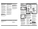
TIJERAS
Si fuera posible, separe las tijeras para
que el afilado sea más fácil y seguro.
Quite el material de la superficie
exterior ÚNICAMENTE. NO afile la
superficie interna de las tijeras.
Trabaje desde el extremo pesado
(grueso) de las tijeras hacia la punta
(vea la figura 7).
29 Sp
Figura 7
Figura 6
DG490500CK, DG490700CK
Safety Rules for
Bench Grinders (Cont’d.)
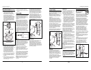
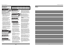
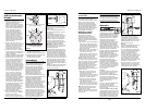
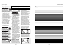
6. Be sure the wheel you intend to
mount as a replacement has no
cracks, chipped areas or defects.
Mount wheel on a rod or pencil
through arbor hole and tap the side
of the grinding wheel (in the
positions shown in Figure 4) with a
light, non-metallic implement such as
the handle of a screwdriver. A sound
and undamaged wheel will give a
clear tone. If cracked, there will be a
dead or dull sound and not a clear
ring. If damaged, the wheel should
not be used.
7. As the grinding wheel diameter
decreases with use, the position of
the work rest should be adjusted.
Optimally, the distance between the
outer diameter of the grinding
wheel and the inner edge of the
work rest should be less than the
thickness of the material being
ground but not more than 1/8"
(3 mm). If not, loosen the two
retaining bolts with each work rest,
set the correct gap, and fully tighten.
8. For safe use, keep the standard-
equipped eye shields in position at
all times.
9. Before switching on the grinder,
turn the grinding wheel by hand to
make sure it is not striking the
work or tool rest.
10. Always use guards and eye shields.
11. Do not over tighten wheel nut.
12. Use only flanges furnished with the
grinder.
Assembly
Before assembling the packaged parts,
carefully check the parts for damage. If
the parts (e.g. guards) are damaged to
the point where they no longer
perform their intended function, they
should be properly repaired or
replaced.
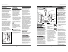
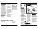
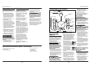
With the grinder disconnected from
the power supply and when working
with the right side of the grinder first,
position the spark arrester shown in
Figure 5 onto the inner metal grinding
wheel guard and attach it via the
smaller supplied hex bolt, lockwasher,
and flat washer. The mounting hole for
this bolt is the smaller diameter one on
the top of the inner guard, nearest the
user. Tighten the securing bolt so that
the spark arrester is close to, but not
touching the grinding wheel. A gap
between the two parts should be
maintained at approximately 1/16 inch
[1.5mm].
Using the remaining bolt hole on the
top of the inner wheel guard, then
attach the eye shield via the bolt with
the black knob and the metal adapter
which fits over the U-shaped support.
Secure the eye shield by hand
tightening the black knob.
Note: The eye shield should be
centered over the grinding wheel in
this position. If not, use the other
supplied eye shield assembly.
If there is any protective material over
the clear eye shield, remove it at this
time.
The work rests are now to be installed
via the two remaining bolt holes in the
bottom of the inner guard and the
larger supplied hex bolts, lockwashers,
and flat washers. Two of each should
be used to secure each work rest.
Note: The work rest which has the drill
bit groove stamped at an angle in it
should be used for the right hand
assembly.
The inner edge of the work rest should
be positioned so that its distance from
the outer diameter of the grinding
wheel is less than the thickness of the
material to be ground, but not more
than 1/8 inch [3mm]. Once this distance
is set, securely tighten both retaining
bolts. When complete, spin the
grinding wheel by hand to insure that
none of these assembled parts contact
the wheel. The finished assembly
should look like that shown in Figure 6.
Repeat the process for assembling the
remaining supplied parts to the left
side of the grinder.
Mounting
If the bench grinder has a tendency to
tip over, slide, or walk on the
supporting surface, then it should be
securely mounted. To do so, first make
sure that the grinder is disconnected
from the power supply. Then secure the
bench grinder using the mounting holes
provided in the base of the grinder and
screws (not provided).
4
www.chpower.com
Figure 5
Operating Instructions
Figure 6
Figure 4
45°
45°
45°
45°
Heavy wheels - support
on clean hard floor
Light wheels - support from
hole by small pin or finger
“TAP”
HERE
“TAP”
HERE