


6
www.chpower.com
Operating Instructions and Parts Manual
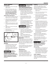
GROUNDING
1. Use the ground terminal and wing
nut on the welder / generator frame
to connect the unit to a suitable
ground source. Securely fasten the
end terminal of the ground wire to
the ground terminal on the
welder / generators frame. Tighten
the washer and wing nut on top of
the ground wire end terminal.
2. The ground wire should be made
of #8 gauge wire. Do not use wire
with a higher gauge number.
Higher gauge numbers indicate
thinner wire, which may not
provide an adequate ground path.
3. The other end of the ground wire
must be securely fastened to an
approved ground source.
The following are ground sources
approved by the National Electric
Code. Other ground sources may be
acceptable. Refer to the National
Electric Code and local regulations for
further ground source information. If
not sure of regulations or procedures,
obtain assistance from a qualified
(licensed or certified) electrical
technician.
a. An underground water pipe at
least ten feet in length
b. A non-corrosive underground
pipe at least eight feet in length
and 3/4 inch diameter
c. A steel or iron underground rod
at least eight feet in length and
5/8 inch diameter
d. A non-ferrous rod at least
eight feet in length, 1/2 inch
in diameter, and approved for
grounding purposes
Any rod or pipe used for grounding
must be driven to eight feet deep or
buried in the deepest possible trench.
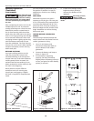
STARTING
1. Remove all electrical loads from the
welder / generators.
2. Move fuel shut-off lever as far as
possible to the right to enable fuel
flow.
3. Rotate the engine switch to the ON
position.
4. Adjust the choke lever as follows:
a. For cold engine, move the choke
lever as far as possible to the left,
choke fully ON, position.
b. For warm / hot engine, move the
choke lever midway between the
choke and run positions.
5. Pull the starter rope with a brisk,
smooth motion.
NOTE: Some models may be
equipped with an electric starter.
For models equipped with an
electric starter, turn the key.
6. After each start up, allow the
engine to run for 2-3 minutes with
no load.
7. As the engine warms up and
stabilizes, adjust the choke lever
to the right, until the lever is
positioned as far as possible to the
right.
Engine speed is
preset to provide
proper output voltage. Never attempt
to modify or adjust engine speed or
output voltage.
ENGINE BREAK-IN
After initial start-up, the engine
should be broken in according to the
manufacturer's instructions. Refer to the
engine manual for the proper break-in
procedure.
SHUT-OFF
1. Shut off and remove all electrical
load devices from the welder /
generator.
2. Allow the engine to run for 2-3
minutes with no electrical loads.
3. Rotate the engine switch to the OFF
position.
4. Verify that the welder / generator
has completely stopped.
5. Close the fuel supply valve.
6. Allow the unit to cool before
installing any covers.
Pre-Operation
LOCATION
Selecting the proper location can
significantly increase performance,
reliability and life of the arc welder.
• For best results locate the welder /
generator in an environment that is
clean and dry. Dust and dirt in the
unit retain moisture and increase
wear of moving parts.
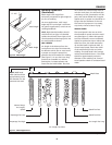
• Store electrodes in a clean, dry
location with low humidity to
preserve the flux coating.
INSTRUCTIONS
1. Check engine oil level. Oil is NOT
mixed with the gasoline, however
adequate oil supply is necessary for
proper engine lubrication. Refer to
the Engine Manual for SAE, API and
fill quantity specifications. Unit is
shipped without oil in engine.
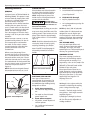
2. Use of a Ground Fault Interrupter
(GFI) is strongly recommended.
Ground Fault Interrupters can
significantly reduce the possibility
of injury if an electrical short occurs.
In order to install a GFI, the
welder / generators neutral wire
must be internally grounded to the
welder / generators frame, and the
frame must be properly grounded
to the earth.
A Ground Fault
Interrupter may
not be effective if used on a welder /
generators that is not grounded! Refer
to the section entitled Grounding for
proper steps to ground the welder /
generator.
3. When installing a GFI, be sure
to follow all national and
local regulations. If not sure of
regulations or procedures, obtain
assistance from a qualified (licensed
or certified) electrical technician.