


8
www.chpower.com
Operating Instructions and Parts Manual
Generator Operation
(Continued)
INSTALLATION FOR STAND-BY USE
Precautions must be taken to prevent
electrical back feeding into utility
systems. This requires isolation of
the electrical system. To isolate the
electrical system, perform the following
procedures:
1. Turn off the main electrical system
switch prior to connecting the
welder / generators.
2. In accordance with national and
local standards, a double throw
transfer switch must be installed in
the system.
Always shut off
main power prior to
temporary connection of the welder /
generators to a building electrical
system.
Installation of the
welder / generator
as a backup electrical source must be
performed by a qualified (licensed or
certified) electrical technician.
Welder Operation
(FRONT PANEL SWITCH MUST BE SET TO
WELDER POSITION)
WELDING LEAD ASSEMBLIES
Welding leads assemblies are not
included with all units. Use copper
welding cables in the size specified in
Table 3.
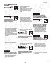
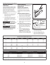
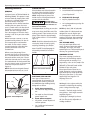
GROUND CLAMP (SEE FIGURE 1)
1. Strip 1/2 inch of insulation from the
end of one of the welding cables.
2. Loosen hex nuts on work clamp.
3. Insert the end of the welding cable
through clamp handle and slide the
bare wire under the clamp block.
4. Tighten the hex nuts, securing the
cable in place.
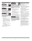
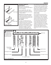
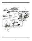
ELECTRODE HOLDER (SEE FIGURE 2)
1. Strip 1/2 inch of insulation from the
end of the other welding cable.
Slide the bare wire into the wire
sleeve.
2. Loosen the phillips head screw
a few turns. Do not remove it
completely. Pull the insulated
handle off of the electrode holder,
and slide it over the welding cable.
3. Loosen the set screw on the bottom
of the electrode holder.
4. Insert the welding cable / wire
sleeve into the back of the brass
body of the electrode holder.
Figure 1
Electrode Holder
Handle Phillips Head Screw
Handle
Cable Setscrew
Wire
Sleeve
Welding
Cable
Figure 2
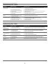
TABLE 3 - WELDING CABLES
Total Cable Length * 0 - 20 feet (0 - 6 m) 20 - 40 feet (6 - 12 m) 40 - 60 feet (12 - 18 m)
Maximum Welding Current Recommended Sizes of Copper Welding Cables
100 A 6 AWG (15 mm
2
) 6 AWG (15 mm
2
) 4 AWG (20 mm
2
)
150 A 6 AWG (15 mm
2
) 3 AWG (25 mm
2
) 2 AWG (35 mm
2
)
200 A 4 AWG (20 mm
2
) 2 AWG (35 mm
2
) 1 AWG (40 mm
2
)
250 A 3 AWG (25 mm
2
) 2 AWG (35 mm
2
) 1/0 AWG (55 mm
2
)
* Total cable length is the sum of the ground and electrode cable lengths.
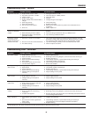
TABLE 2 - EXTENSION CORDS
Maximum Recommended Lengths (in feet)
Amps Watts 120 V Watts 240 V #8 Wire #10 Wire #12 Wire #14 Wire #16 Wire
2.5 300 600 1000 600 375 250
5 600 1200 500 300 200 125
7.5 900 1800 350 200 125 100
10 1200 2400 250 150 100 50
15 1800 3600 150 100 65
20 2400 4800 175 125 75 50
25 3000 6000 150 100 60
30 3600 7200 125 65
40 4800 9600 90