


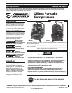
HM7500 and HM7510
3
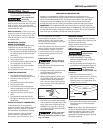
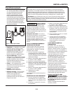
SPRAYING PRECAUTIONS
Do not spray
flammable materials
in vicinity of open flame or near ignition
sources including the compressor unit.
24. Spray in a well ventilated area, to keep
fumes from collecting and causing
health and fire hazards.
25. Do not spray in vicinity of open flames
or other places where a spark can
cause ignition. Do not smoke when
spraying paint, insecticides, or other
flammable substances.
26. Use a respirator when spraying.
27. Do not direct paint or other sprayed
material at the compressor. Locate
compressor as far away from
the spraying area as possible to
minimize overspray accumulation
on the compressor.
28. When spraying or cleaning with
solvents or toxic chemicals, follow
the instructions provided by the
chemical manufacturer.
29. Do not smoke when spraying paint,
insecticides, or other flammable
substances.
30. Use a face mask/
respirator when spraying
and spray in a well
ventilated area to
prevent health and fire
hazards.
31. Household use only.
32. To reduce the risk of electrical shock,
do not expose to rain. Store indoors.
Assembly
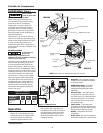
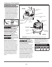
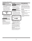
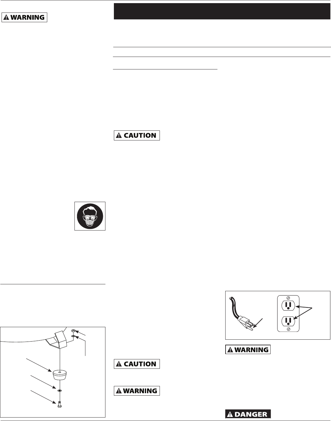
FOOT ASSEMBLY (FIGURE 1)
Foot assembly kit includes:
- 3 rubber feet
- 3 bolts
- 6 washers
- 3 nuts
Installation
LOCATION
It is extremely important to install the
compressor in a clean, well ventilated area
where the surrounding air temperature
will not be more than 100°F.
A minimum clearance of 18 inches between
the compressor and a wall is required
because objects could obstruct air flow.
Do not locate the
compressor air inlet
near steam, paint spray, sandblast areas
or any other source of contamination. This
debris will damage the motor.
Household use only. Store indoors.
ELECTRICAL INSTALLATION
1. Check and tighten all bolts, fittings,
etc., before operating compressor.
2. Operate compressor in a ventilated
area so that compressor may be
properly cooled.
3. Compressor should be located where
it can be directly plugged into an
outlet, but if this is not possible, an
extension cord may be used. It should
be selected using the extension cord
chart on page 3 as a guide.
4. To avoid loss of power and
overheating, it is better to use
additional air hose instead of
extension cords to reach work area.
WIRING
1. Local electrical wiring codes
differ from area to area. Source
wiring, plug and protector must
be rated for at least the amperage
and voltage indicated on motor
nameplate, and meet all electrical
codes for this minimum .
2. Use a slow blow fuse type T or a
circuit breaker.
Overheating, short
circuiting and fire
damage will result from inadequate
wiring, etc.
All wiring and
electrical
connections should be performed by a
qualified electrician. Installation must
be in accordance with local codes and
national electrical codes.
NOTE: 120 volt, compressor can be
operated on a 120 volt, 15 amp circuit
under the following conditions:
a. No other electrical appliances or
lights are connected to the same
branch circuit.
b. Voltage supply is normal.
c. Extension cords are of the
minimum gauge specified in this
instruction manual.
d. Circuit is equipped with a 15 amp
circuit breaker or a 15 amp slow
blow fuse type T.
3. If above conditions cannot be met
or if nuisance tripping of current
protection device occurs, it may be
necessary to operate compressor
from a 120 volt, 20 amp circuit.
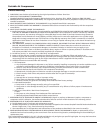
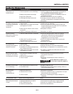
GROUNDING INSTRUCTIONS
This product must be grounded. In
the event of an electrical short circuit,
grounding reduces the risk of electric
shock by providing an escape wire
for the electric current. This product
is equipped with a cord having a
grounding wire with an appropriate
grounding plug. The plug must be
plugged into an outlet that is properly
installed and grounded in accordance
with all local codes and ordinances.
Improper installation
of the grounding plug
is able to result in a risk of electric shock.
When repair or replacement of the cord or
plug is required, do not connect the
grounding wire to either flat blade
terminal. The wire with insulation having
an outer surface that is green with or
without yellow stripes is the grounding
wire.
Do not use adapter
with this product!
Power cord White Line No
Motor cord White Load No
Power cord Black Line Yes
Motor cord Black Load Yes
✽ Wire and Terminal Guide
Wire Color Terminal Hot
(✽) When the unit is not in operation
TEST
RESET
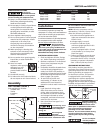
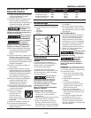
Figure 2 - Grounding Method
Grounding
Pin
Grounded
Outlet
www.chpower.com
Rubber Foot
Washer
Bolt
Washer
Nut
Figure 1 - Rubber foot installation