


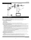

Flux Core Wire Installation
Welding power
is applied to the
output terminals, feed roll, work clamp,
gun cable connection and welding wire
even when the the gun switch is not
activated. Do not touch these parts
when the welding machine is on.
NOTE: Before installing welding wire,
be sure that the diameter of the
welding wire matches the contact tip in
the end of the gun. The wire size is
marked on the contact tip in inches or
mm. (See chart below).
1. Verify the unit is off and lift the door
on the welder to expose the wire
feed mechanism.
2. Remove the spool quick lock, by
pushing in and rotating 1/4 turn
counterclockwise. The knob, spring,
and spool spacer can now be removed.
3. Loosen the wire feed tensioning
screw on the drive mechanism. This
allows initial feeding of the wire into
the gun liner by hand.
4. Install the wire spool onto the
spindle so that the wire can come off
the spool on the end closest to the
wire feed guide tube. Do not cut
the wire loose yet. Install the spool
spacer, spring, and quick lock knob
by pushing in and turning the knob
1/4 rotation clockwise.
5. Hold the wire and cut the wire end
from the spool. Do not allow the wire
!
WARNING
to unravel. Be sure that the end of the
wire is straight and free of burrs.
6. Feed the wire through the wire feed
guide tube, over the groove in the
drive roll and into the gun liner.
Tighten the wire feed tensioning
screw so that it is snug. Do not over
tighten.
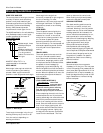
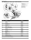
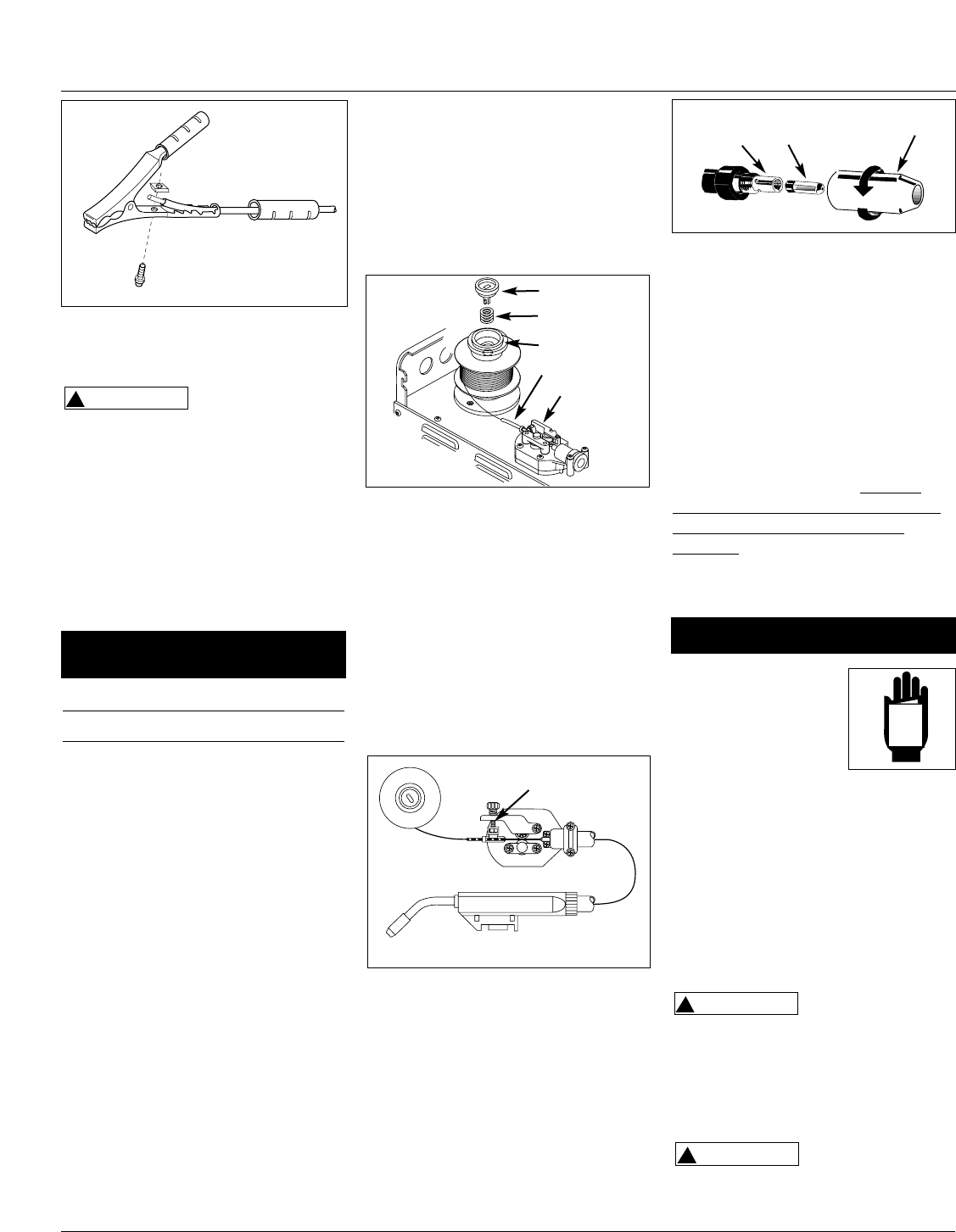
7. Remove the nozzle by turning
counterclockwise. Then, unscrew the
contact tip from the end of the
welding torch. (See Figure 6). Plug
the welder into the proper power
supply receptacle.
8. Turn on the welder and set the wire
speed rate to 8. Activate the gun
switch until the wire feeds out past
the torch end. (See Figure 5.) Turn
welder off.
9. Carefully slip the contact tip over the
wire and screw it into the torch
diffuser. (See Figure 6.) Install the
nozzle by twisting clockwise. Cut the
wire off approximately 1/4 inch from
the end of the nozzle.
4
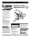
Wire Feed Arc Welder
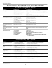
DUTY CYCLE / THERMOSTATIC
PROTECTION
Welder duty cycle is the percentage of
actual weld time that can occur in a ten
minute interval. For example, at a 10%
duty cycle, actual welding can occur for
one minute, then the welder must cool
for nine minutes.
Internal components of this welder are
protected from overheating with an
automatic thermal switch. A yellow
lamp is illuminated on the front panel
(on/off switch) if the duty cycle is
exceeded. Welding operations may
continue when the yellow lamp is no
longer illuminated.
1. Be sure to read,
understand, and
comply with all
precautions in the
General Safety
Information section and Welding
Guidelines prior to using this
equipment.
2. Verify welder is off.
3. Verify that the surfaces of metals to
be joined are free from dirt, rust,
paint, oil, scale or other
contaminants. These contaminants
make welding difficult and cause
poor welds.
All persons
operating this
equipment or in the area while
equipment is in use must wear
protective welding gear including: eye
protection with proper shade, flame
resistant clothing, leather welding
gloves, and full foot protection.
The welding wire is
live whenever the
welder is turned on—whether or not
the trigger is pulled.
!
CAUTION
!
WARNING
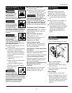
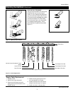
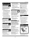
Figure 4 - Weld Wire Routing
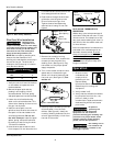
Torch
Diffuser
Contact Tip
Nozzle
Figure 6 - Torch Nozzle
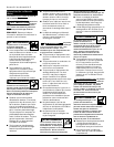
Figure 3 - Work Clamp Assembly
Contact Tip Markings
Wire Size mm
.030” or .8
.035” or .9
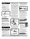
Figure 5 - Wire Feed Gun
Operation
MANUAL
Spool Lock
Spool Spring
Spacer
Guide Tube
Tension Screws
Tension Screw
www.chpower.com