


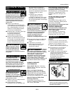
Metal Heat
Thickness Setting
5
Model WF2010
If heating, welding, or
cutting materials that are
galvanized, zinc plated,
lead, or cadmium plated
refer to the General Safety Information
Section for instructions. Extremely
toxic fumes are created when these
metals are heated.
4. Connect the work clamp to the
work piece or workbench (if metal).
Make sure the contact is secure.
Avoid surfaces with paint, varnish,
corrosion, or non-metallic materials.
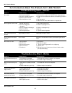
5. Position the Heat Selector on the
front panel to the desired setting.
NOTE: These settings are general
guidelines only. Heat setting may vary
according to welding conditions and
materials.
6. Rotate the Wire Speed Control to
setting number 5 to start with, then
adjust as needed after test weld.
7. Plug the input cord into a proper
voltage receptacle with proper
circuit capacity. (See Chart under
circuit requirements on page 1).
8. Switch the welder ON/OFF switch to
the ON position.
9. Verify that the wire is extended
1/4” from the contact tip. If not,
squeeze the trigger to feed
additional wire, release the trigger,
and cut wire to proper length.
10. Position the wire feed gun near the
work piece, lower the welding
helmet by nodding the head, or
position the hand shield, and
squeeze the gun trigger. Adjust heat
setting and wire speed as needed.
11. When finished welding, turn welder
off and store properly.
!
WARNING
Disconnect power
supply and turn
machine off before inspecting or
servicing any components. Keep the wire
compartment cover closed at all times
unless the wire needs replacement.
Before every use:
1. Check condition of weld cables and
immediately repair or replace any
cables with damaged insulation.
2. Check condition of power cord and
immediately repair or replace any
cord if damaged.
3. Inspect the condition of the gun tip
and nozzle. Remove any weld slag.
Replace gun tip or nozzle if
damaged.
Do not operate this
welding machine
with cracked or missing insulation on
welding cables, wire feed gun, or
power cord.
Every 3 months:
1. Replace any unreadable safety
labels on the welder.
2. Use compressed air to blow all dust
and lint from the ventilation
openings.
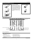
3. Clean the wire groove on the drive
roll. Remove wire from the feed
mechanism, remove screws from
the drive roll housing. Use a small
wire brush to clean the drive roll.
Replace if worn or damaged.
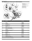
Consumable and Wear Parts
The following parts require routine
maintenance:
• Wire feed drive roller
• Gun liner - replace if worn
• Nozzle/contact tips
• Wire - This welder will accept either
4” or 8” diameter spools. Flux-cored
welding wire is susceptible to moisture
and oxidizes over time, so it is
important to select a spool size that
will be used within approximately 6
months. Use AWS type AWS E71T-GS
or E71T-11, .030" (.8mm) or .035"
(.9mm) diameter.
Call (800) 746-5641
for replacement parts
!
WARNING
!
WARNING
Operation
(Con’t)
14-20 Gauge Low
Thicker than 14 Gauge High
Maintenance
Welding Guidelines
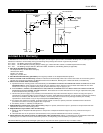
General
This line of welding machines utilizes
the Flux Cored Arc Welding (Gasless)
process. The weld must be protected
(shielded) from contaminates in the air
while it is molten. The gasless process
uses a tubular wire with a flux material
inside. The flux creates a shielding gas
when melted.
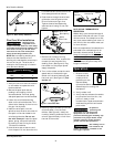
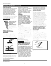
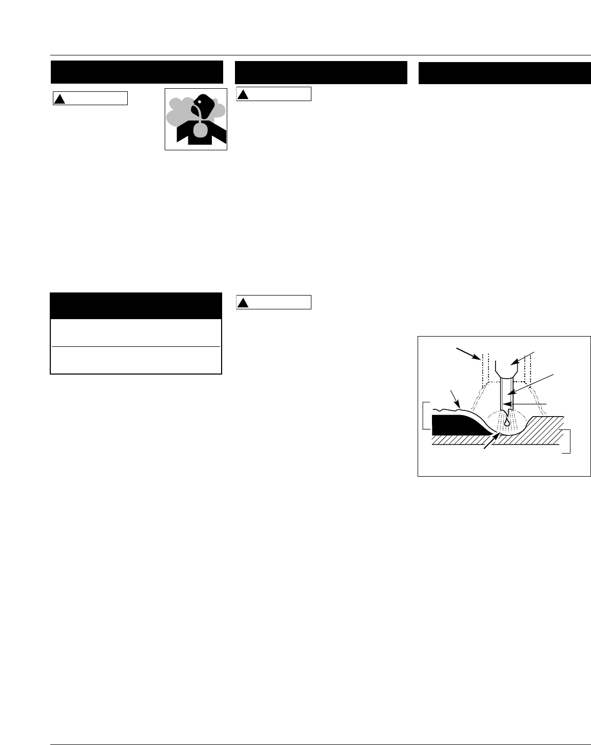
When current is produced by a
transformer (welding machine) and
flows through the circuit to the weld
wire, an arc is formed between the end
of the weld wire and the work piece.
This arc melts the wire and the work
piece. The melted metal of the weld
wire flows into the molten crater and
forms a bond with the work piece as
shown (Figure 7).
Arc Welding Basics
Five basic techniques affect weld
quality. These are: wire selection, heat
setting, weld angle, wire speed, and
travel speed. An understanding of
these techniques is necessary for
effective welds.
HEAT SETTING
The correct heat involves the
adjustment of the welding machine to
the required setting. The heat setting
used depends on the thickness of the
work piece. Consult specifications listed
on the welder. It is suggested that the
welder practice with scrap metal to
adjust settings, and compare welds
with Figure 12.
Slag
Weld
Wire
Flux
Work Piece
Contact
Tip
Crater
Nozzle
Figure 7 - Weld Components
www.chpower.com