


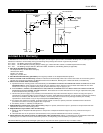
WIRE TYPE AND SIZE
The correct choice of wire type involves
a variety of factors, such as welding
position, work piece material type,
thickness, and condition of surface to
be welded. The American Welding
Society, AWS, has set up certain
requirements for each type of wire.
The AWS classification for self-shielding
wire (Gasless process) is a multi digit
number preceded by the letter E.
FLUX-CORED WIRE
E - 7
0 T
- GS
Weld strength, times
10,000 pounds per
square inch
Welding positions (0
for flat or horizontal,
1 for any position)
Tubular flux core wire
Flux type
AWS E71T-GS or E71T-11 is
recommended for this welder.
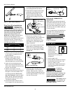
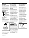
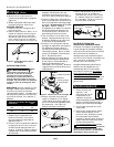
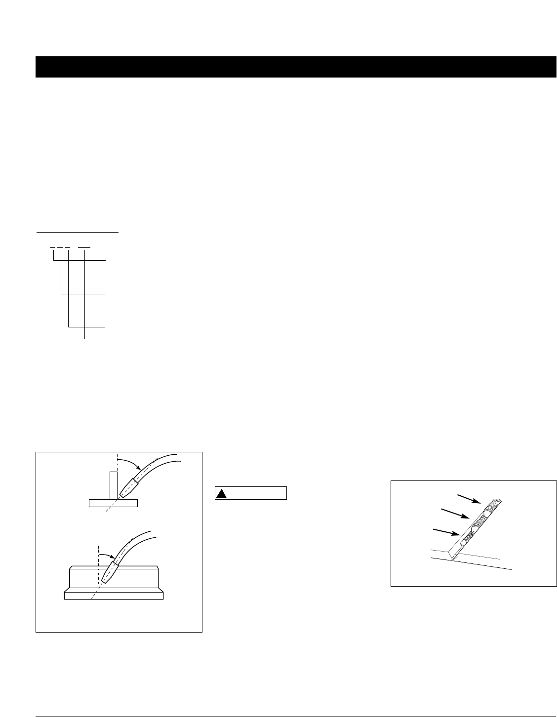
WELD ANGLE
Weld angle is the angle at which the
nozzle is held during the welding
process. Weld angle involves two
positions - travel angle and work angle.
Travel angle is the angle in the line of
welding and may vary from 5º to 45º
from the vertical, depending on
welding conditions.
6
Wire Feed Arc Welder
Work angle is the angle from
horizontal, measured at right angles to
the line of welding. For most
applications, a 45º travel angle and 45º
work angle is sufficient. For specific
applications, consult an arc welding
handbook.
WIRE SPEED
The wire speed is controlled by the
knob on the front panel. The speed
needs to be “tuned” to the rate at
which the wire is being melted in the
arc. Too slow of speed will cause
sputtering and the wire will burn up
into the contact tip. Too fast a speed will
also cause a sputtering sound and the
wire will push into the plate before
melting.
TRAVEL SPEED
The travel speed is the rate at which
the torch is moved across the weld
area. Factors such as diameter and type
of weld wire, amperage, position, and
work piece material thickness all effect
the speed of travel necessary for
completing a good weld (See Fig. 12).
When the speed is too fast, the bead is
narrow and bead ripples are pointed as
shown. When the speed is too slow, the
weld metal piles up and the bead is
high and wide.
SLAG REMOVAL
(FLUX-CORED WIRE ONLY)
Wear ANSI
approved safety
glasses (ANSI Standard Z87.1) and
protective clothing when removing
slag. Hot, flying debris can cause
personal injury to anyone in the area.
After completing the weld, wait for the
welded sections to cool. A protective
coating called slag now covers the weld
bead which prevents contaminants in
the air from reacting with the molten
metal. Once the weld cools to the point
that it is no longer glowing red, the
slag can be removed. Removal is done
with a chipping hammer. Lightly tap
the slag with the hammer and break it
loose from the weld bead. The final
!
WARNING
Welding Guidelines (Continued)
clean-up is done with a wire brush.
When making multiple weld passes,
remove the slag before each pass.
WELDING POSITIONS
Four basic welding positions can be
used; flat, horizontal, vertical, and
overhead. Welding in the flat position
is easier than any of the others because
welding speed can be increased, the
molten metal has less tendency to run,
better penetration can be achieved,
and the work is less fatiguing. Welding
is performed with the wire at a 45º
travel angle and 45º work angle.
Other positions require different
techniques such as a weaving pass,
circular pass, and jogging. A higher skill
level is required to complete these welds.
All work should be performed in the
flat position if possible. For specific
applications, consult an arc welding
technical manual.
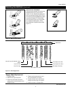
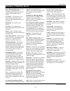
WELD PASSES
Sometimes more then one pass is
necessary to fill the joint. The root pass
is first, followed by filler passes and the
cover pass. (See Figures 9 and 10.) If the
pieces are thick, it may be necessary to
bevel the edges that are joined at a 60º
angle. Remember to remove the slag
before each pass.
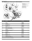
TRAVEL ANGLE
WORK ANGLE
5º - 45º
5º - 45º
Figure 8 - Weld Angle
Figure 9 - Weld Passes
Cover
Filler
Root
www.chpower.com