


Wire Feed Arc Welder
8
www.chpower.com
WIRE SPEED
The wire speed is controlled by the knob
on the front panel. The speed needs to
be “tuned” to the rate at which the wire
is being melted in the arc. Tuning is one
of the most critical functions of wire feed
welding. Tuning should be performed on
a scrap piece of metal the same type and
thickness as that to be welded. Begin
welding with one hand “dragging” the
torch nozzle across the scrap piece while
adjusting the wire speed with the other
hand. Too slow of speed will cause
sputtering and the wire will burn up into
the contact tip. Too fast a speed will also
cause a sputtering sound and the wire
will push into the plate before melting. A
smooth buzzing sound indicates the wire
speed is properly tuned. Repeat the
tuning procedure each time there is a
change in heat setting, wire diameter or
type, or work piece material type or
thickness. For Aluminum, wire speed is
typically set higher (7-9 speed range).
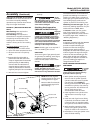
TRAVEL SPEED
The travel speed is the rate at which the
torch is moved across the weld area.
Factors such as diameter and type of weld
wire, amperage, position, and work piece
material thickness all affect the speed of
travel necessary for completing a good
weld (See Figure 7). When the speed is
too fast, the bead is narrow and bead
ripples are pointed as shown. When the
speed is too slow, the weld metal piles up
and the bead is high and wide. For
Aluminum, travel speed is typically faster.
ELECTRODE EXTENSION
Electrode extension (or electrode stick-
out) is the distance between the end of
the contact tip and and the end of the
welding wire. The recommended
electrode extension is from 1/4 to 1/2
in (6 to 13 mm). If the electrode
extension is too long, welding current
will be reduced and the bead will be
high and narrow with less penetration.
SLAG REMOVAL
(FLUX-CORED WIRE ONLY)
Wear ANSI approved safety
glasses (ANSI Standard Z87.1)
and protective clothing when
removing slag. Hot, flying
debris can cause personal injury to
anyone in the area.
After completing the weld, wait for the
welded sections to cool. A protective
coating called slag now covers the weld
bead which prevents contaminants in
the air from reacting with the molten
metal. Once the weld cools to the point
that it is no longer glowing red, the
slag can be removed. Removal is done
with a chipping hammer. Lightly tap
the slag with the hammer and break it
loose from the weld bead. The final
clean-up is done with a wire brush.
When making multiple weld passes,
remove the slag before each pass.
WELDING POSITIONS
Four basic welding positions can be used;
flat, horizontal, vertical, and overhead.
Welding in the flat position is easier than
any of the others because welding speed
can be increased, the molten metal has less
tendency to run, better penetration can be
achieved, and the work is less fatiguing.
Welding is performed with the wire at a
45º travel angle and 45º work angle.
Other positions require different
techniques such as a weaving pass,
circular pass, and jogging. A higher skill
level is required to complete these welds.
Overhead welding is the least desirable
position as it is the most difficult and
dangerous. Heat setting and wire selection
will vary depending upon the position.
All work should be performed in the
flat position if possible. For specific
applications, consult an arc welding
technical manual.
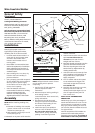
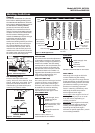
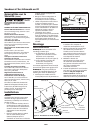
WELD PASSES
Sometimes more than one pass is necessary
to fill the joint. The root pass is first,
followed by filler passes and the cover pass.
If the pieces are thick, it may be necessary
to bevel the edges that are joined at a 60º
angle. Remember to remove the slag
before each pass for the FCAW process.
Welding Guidelines (Continued)
Figure 8 - Weld Passes
Cover
Filler
Root
Figure 9 - Multiple Weld Passes
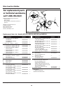
ALUMINUM WELDING
Any aluminum surface to be welded,
must be cleaned thoroughly with a
stainless steel brush to eliminate any
oxidation on the weld and grounding
surface. 100% Argon shielding gas
must be used when welding aluminum.
If 100% Argon is not used, metal
penetration is unlikely. A
PTFE wire liner,
smooth-groove drive roller and
aluminum contact tips are
recommended when welding
aluminum. Campbell Hausfeld offers
these parts in Kit WT2531. Call 1-800-
746-5641 to order.
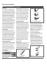
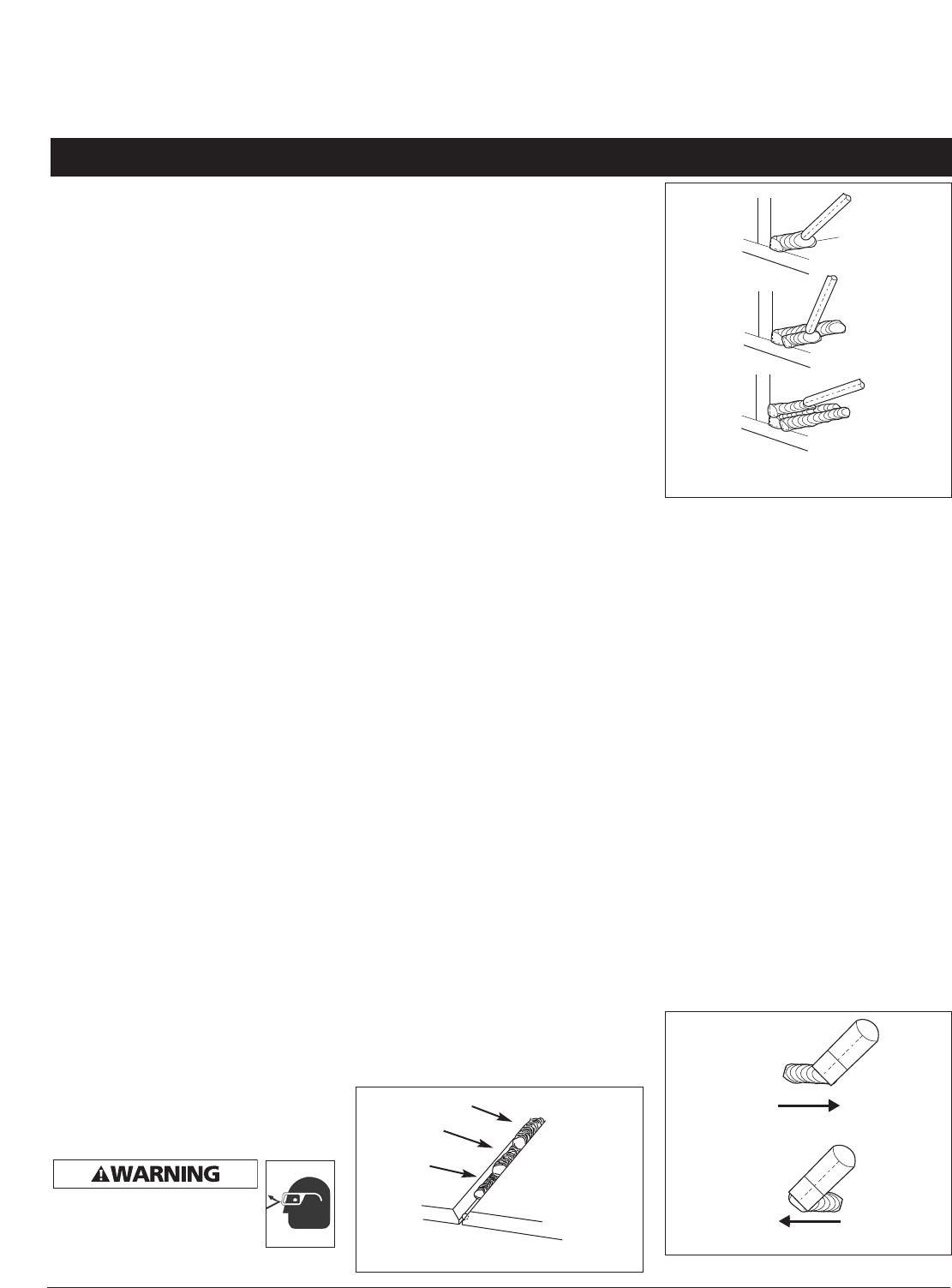
PUSH VS PULL TECHNIQUE
The type and thickness of the work piece
dictates which way to point the torch
nozzle. For thin materials (18 gauge and
smaller) and all aluminum, the nozzle
should point out in front of the weld
puddle and push the puddle across the
workpiece. For thicker steel, the nozzle
should point into the puddle to increase
weld penetration. This is called backhand
or pull technique (See Figure 10).
PUSH
PULL
Figure 10