


The compressor should be checked
often for any visible problems and the
following maintenance procedures
should be performed each time the
compressor is used.
1. Pull ring on safety valve and allow it
to snap back to normal position.
Safety valve must
be replaced if it
cannot be actuated or it leaks air after
ring is released.
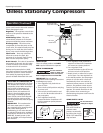
2. With compressor shut off and
pressure released: Drain moisture
from tank by opening drain cock
underneath tank (See Figure 7).
3. Turn power OFF and clean dust and
dirt from motor, tank, air
lines and pump cooling fins.
IMPORTANT: Unit should be located as
far from spraying area as hose will
allow to prevent over-spray from
clogging filter.
AIR FILTER
Check air filter to be sure it is clean. To
service a filter, remove the filter
housing cover. Remove filter and clean
in hot, soapy water (Paper filters
cannot be washed). Rinse and let dry.
Replace air filters that cannot be
cleaned. Place filter back in the housing
base. Replace cover.
LUBRICATION
This is an oilless type compressor
requiring no lubrication.
THERMAL OVERLOAD PROTECTOR
This compressor is
equipped with an
automatic reset thermal overload
protector which will shut off motor if it
becomes overheated.
WL6000 Series
5
Operating Instructions
If thermal overload protector shuts
motor OFF frequently look for the
following causes
1. Low voltage
2. Clogged air filter
3. Lack of proper ventilation
If the thermal
overload protector
is actuated, the motor must be allowed
to cool down before start-up is pos-
sible. The motor will automatically
restart without warning if left plugged
into electrical outlet and unit is
turned on.
TORQUE REQUIREMENTS
Connecting rod bolt . . . . . . . . 20 in. Ibs.
Compressor hd. bolts. . . 100-110 in. Ibs.
Motor bolts . . . . . . . . . . . . . . . 35 in. Ibs.
Mounting bolts . . . . . . . . . . . . 90 in. Ibs.
STORAGE
1. When not in use, store hose and
compressor in a cool, dry place.
2. Drain tank of moisture
3. Disconnect hose and hang open ends
down to allow any moisture to drain.
released, or valve is stuck and cannot
be actuated by ring, it MUST be
replaced.
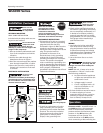
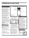
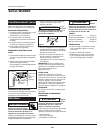
REGULATOR KNOB (See Figure 6)
1. This knob controls air pressure to an
air operated tool, or paint spray gun.
2. Turning knob clockwise increases air
pressure at outlet.
3. Turning counterclockwise will lower
air pressure at outlet.
4. Fully counterclockwise will shut off
flow of air completely.
OUTLET PRESSURE GAUGE
1. This gauge shows at-a-glance, air
pressure at outlet. Air pressure is
measured in pounds per square inch
(PSI).
2. Be sure this gauge reads ZERO before
changing air tools or disconnecting
hose from outlet.
TANK PRESSURE GAUGE
Gauge shows pressure in tank
indicating compressor is building
pressure properly.
Disconnect power
source then release all
pressure from the
system before
attempting to install, service, relocate
or perform any maintenance.
Outlet
Pressure
Gauge
Regulator
Knob
Tank
Pressure
Gauge
(Behind)
Figure 6
Figure 7
Operation (Continued)
Maintenance