


5
Models WS0900, WS0950, WS1000 and WS1020
DUTY CYCLE / THERMOSTATIC
PROTECTION
Welder duty cycle is the percentage of
actual weld time that can occur in a ten
minute interval. For example, at a 10%
duty cycle, actual welding can occur for
one minute, then the welder must cool
for nine minutes.
Internal components of this welder are
protected from overheating with an
automatic thermal switch. A yellow
lamp is illuminated on the front panel
(on/off switch) if the duty cycle is
exceeded. Welding operations may
continue when the yellow lamp is no
longer illuminated.
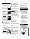
Disconnect power
supply and turn
machine off before inspecting or
servicing any components.
Before every use;
1. Check condition of weld cables and
immediately repair or replace any
cables with damaged insulation.
2. Check condition of power cord and
immediately repair or replace any
cord if damaged.
3. Check condition of electrode holder
insulating pieces and immediately
replace cracked or missing
insulators. Verify that all fasteners
are tight and insulated.
Do not operate this
welding machine
with cracked or missing insulation on
welding cables, electrode holder, or
power cord.
Every 3 months;
Replace any unreadable labels on the
welder. Use compressed air to blow all
dust and lint from the ventilation
openings.
Operation (Con’t) Maintenance
Welding Guidelines
General
This line of welding machines utilizes a
process known as Shielded Metal-Arc
Welding (SMAW). This process is used
to bond metals by heating them with
an electric arc created between the
electrode and the work piece.
Electrodes used for shielded metal arc
welding have two parts. The inner core
is a metal rod or wire that should be
similar in composition to the base
metal. The outer coating is called flux.
Various types of flux exist. Each coating
is used for a particular welding
situation.
While the metal is molten, it can be
contaminated by elements in the air.
This contamination could weaken the
weld. The flux coating creates a
protective barrier called slag that
protects the molten metal from
contaminants.
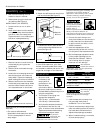
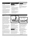
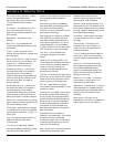
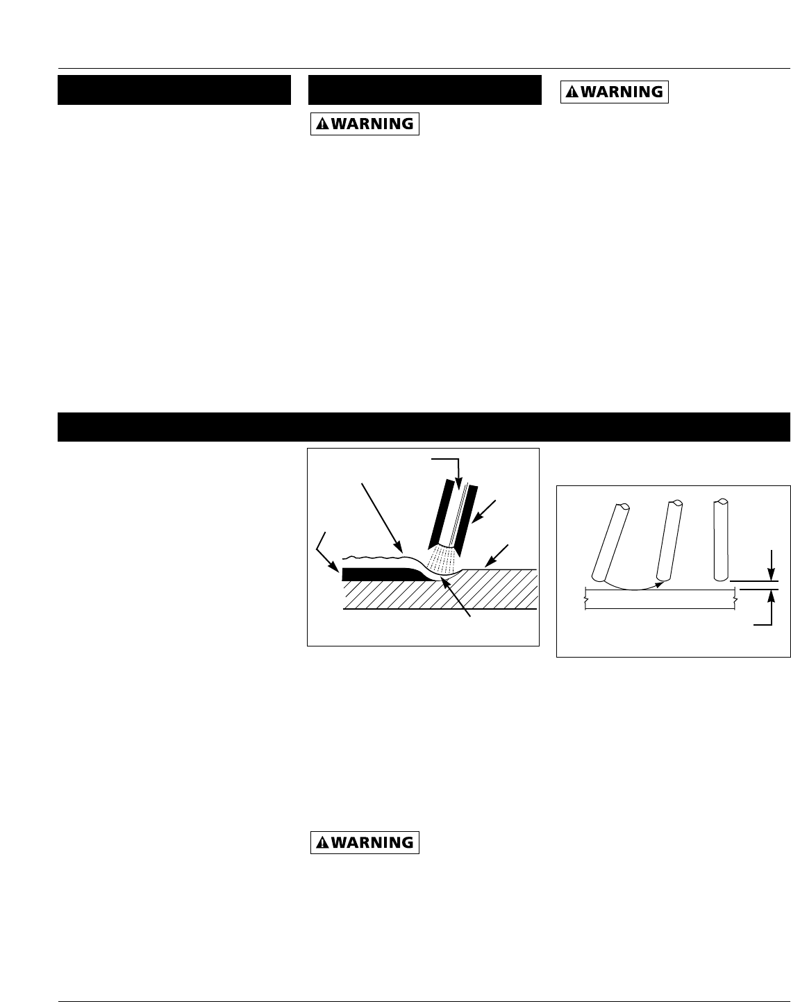
When current (amperage) flows
through the circuit to the electrode, an
arc is formed between the end of the
electrode and the work piece. The arc
melts the electrode and the work piece.
The melted metal of the electrode
flows into the molten crater and forms
a bond with the work piece as shown in
Figure 7.
NOTE: Discontinue using and discard
electrodes that burn down to 1 to 2
inches from the electrode holder.
STRIKING AN ARC
Place the bare end of the electrode in
the holder. Grip the holder lightly to
reduce tiring of the hand and arm.
NOTE: Always keep the jaws of the
holder clean to insure good electrical
contact with the electrode.
Be careful not to
touch the work
piece or welding bench with the
electrode as this causes arc flashes.
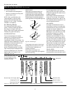
The best method of striking an arc is
the scratching method. Drag the
electrode at an angle along the surface
much like striking a match. Upon
contact with the plate, lift the
electrode approximately 1/16” off the
surface or it will stick (See Figure 8).
NOTE: Should the electrode stick to the
work piece, break it loose by quickly
twisting or bending at the holder while
pulling upward. If the electrode does
not break loose, disengage the
electrode by releasing it from the
holder.
ELECTRODE TYPE AND SIZE
Two types of electrodes are
recommended for this welder. The
electrodes are commonly known by the
AWS (American Welding Society)
designation as follows:
1. E-6013 GENERAL PURPOSE
• All position, smooth deposit rod
with low spatter.
• For all mild steel and general
purpose work.
Slag
Weld
Wire
Flux
Work
Piece
Crater
Figure 7 - Weld Components
Same as Electrode Diameter
Figure 8 - Scratching Method