


7
Models WS0900, WS0950, WS1000 and WS1020
Welding Guidelines (Continued)
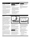
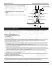
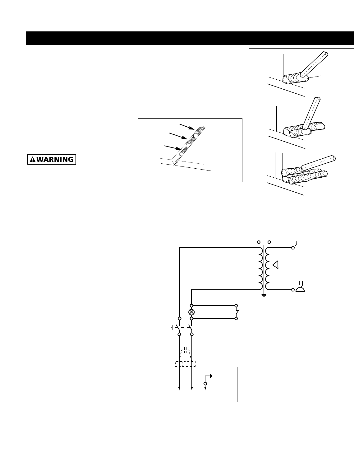
area (See Figure 10). When the speed is
too fast, the bead is narrow and bead
ripples are pointed as shown. When the
speed is to slow, the weld metal piles
up and the bead is high and wide. To
control travel speed, watch the width
of the weld bead (not the arc) when
welding. The weld bead is the orange,
molten metal behind the arc. The width
should be approximately twice the
diameter of the welding rod. Control
travel speed to obtain a consistent
bead width.
SLAG REMOVAL
Wear ANSI
approved safety
glasses (ANSI Standard Z87.1) and
protective clothing when removing
slag. Hot, flying debris can cause
personal injury to anyone in the area.
After completing the weld, wait for the
welded sections to cool. A protective
coating called slag now covers the weld
bead which prevents contaminants in
the air from reacting with the molten
metal. Once the weld cools to the point
that it is no longer glowing red, the
slag can be removed. Removal is done
with a chipping hammer. Lightly tap
the slag with the hammer and break it
loose from the weld bead. The final
clean-up is done with a wire brush.
When making multiple weld passes,
remove the slag before each pass.
WELDING POSITIONS
Four basic welding positions can be used;
flat, horizontal, vertical, and overhead.
Welding in the flat position is easier than
any of the others because welding speed
can be increased, the molten metal has
less tendency to run, better penetration
can be achieved, and the work is less
fatiguing.
Other positions require different
techniques such as a weaving pass,
circular pass, and jogging. A higher skill
level is required to complete these welds.
All work should be performed in the
flat position if possible. For specific
applications, consult an arc welding
handbook.
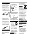
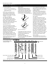
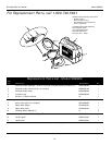
WELD PASSES
Sometimes more then one pass is
necessary to fill the joint. The root pass
is first, followed by filler passes and the
cover pass (See Figure 11). If the pieces
are thick, it may be necessary to bevel
the edges that are joined at a 60º
angle. Remember to remove the slag
before each pass.
Figure 11 - Weld Passes
Cover
Filler
Root
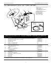
Figure 12 - Multiple Weld Passes
L1
4 1
5
6
2
3
L2
S2
S2
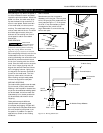
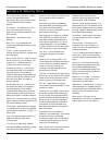
Figure 13 - Wiring Schematic
To Work Clamp
Thermal Breaker
To Electrode
Holder
Thermal Breaker
On/Off
Switch S1
Plug
Black
White
Ground
Green
All Models Except WS0900