


Notes
Notas
8
Model WT2531
Please read and save these instructions. Read carefully before attempting to assemble, install, operate or maintain the product described.
Protect yourself and others by observing all safety information. Failure to comply with instructions could result in personal injury and/or
property damage! Retain instructions for future reference.
IN973400AV 8/05
Installation Instructions Model WT2531
Aluminum
Welding Kit
BUILT TO LAST
Description
Model WT2531 is an aluminum welding
kit designed for use on Campbell
Hausfeld wire feed MIG welders
(WG206X and WG208X series). This kit
includes: Teflon
®
wire liner (Part
Number: WC403621AV) , smooth-
groove drive roller (Part Number:
WC500806AV) , four pieces of 0.030"
(0.8 mm) aluminum contact tips (Part
Number: WT501700AV), and 2
compression seals. These parts, when
installed in your welder, allow welding
aluminum with greater success. Along
with this kit, you will need a spool of
0.030" (0.8 mm) aluminum MIG wire
(Part Number: WE303001AV) and a
bottle of 100% Argon shielding gas
(available from your local welding gas
supplier).
Teflon
®
Wire Liner
The Teflon
®
wire liner reduces the drag
on the soft aluminum welding wire.
DO NOT USE TO WELD STEEL. This
liner should be used for aluminum
welding only to prevent
contamination.
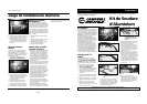
1. Verify the welder is OFF and
UNPLUGGED.
2. Open wire feed door and locate
drive deck. Remove torch cable
cover by removing three screws (see
figure 1).
3. Disassemble torch handle by
removing five screws (see figure 2).
For parts, manuals, product & service information
visit www.chpower.com
or call 1-800-746-5641
© 2005 Campbell Hausfeld/Scott Fetzer
4. Remove swan neck/valve assembly
from handle (see figure 3).
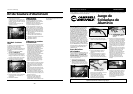
5. Using two 14 mm wrenches, hold
the compression nut and loosen the
jam nut (see figure 4a). Then
remove the compression nut. Slide
the wire liner, compression nut and
compression seal out of the swan
neck being careful not to kink the
wire liner in the process (see figure
4b).
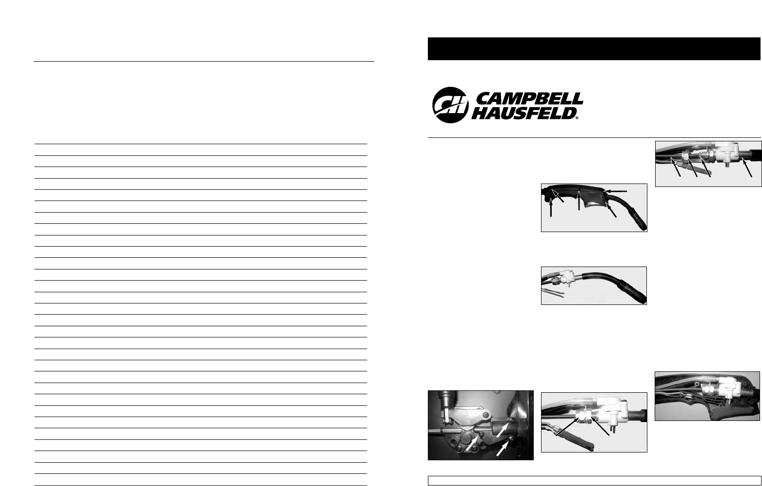
Figure 1 – Remove these three screws
Figure 3
Figure 4a - Hold compression nut (1),
loosen jam nut (2)
Figure 4b - Wire liner (1), compression
nut (2), compression seal (3),
swan neck (4)
Figure 5
(1) (2)
(1)
(2)
(3)
(4)
6. Straighten the torch hose and
remove the existing wire liner,
compression nut and compression
seal. Then remove the compression
nut from the wire liner. Note:
sometimes the compression seal is
stuck to the wire liner; therefore,
new seals are included in this kit.
7. Insert new Teflon wire liner into
torch hose. Slide compression nut
and new compression seal onto wire
liner. Slide wire liner into swan neck
until it stops against the back of the
contact tip. Tighten the compression
nut and then tighten the jam nut.
8. Place swan neck/valve assembly into
torch handle, making sure small
wires are located correctly (see
figure 5). Reassemble torch handle
with five screws
Figure 2 – Remove these five screws
REMINDER: Keep your dated proof of purchase for warranty purposes! Attach it to this manual or file it for safekeeping.