


A-3
INSTALLATION
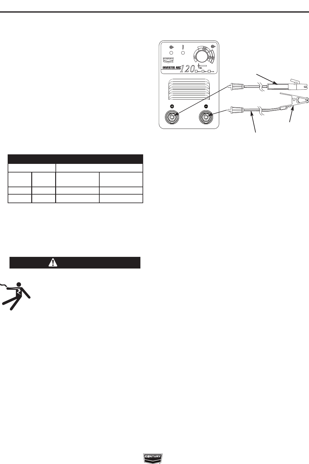
INVERTER ARC™ 120
A-3
OUTPUT CONNECTIONS
A quick disconnect system using Twist-Mate™ cable
plugs is used for the welding cable connections.
ELECTRIC SHOCK can kill.
• Keep the electrode holder and cable
insulation in good condition.
• Do not touch electrically live parts or
electrode with skin or wet clothing.
• Insulate yourself from work and ground.
• Turn the input line Switch on the INVERTER
ARC™ 120 “off” before connecting or discon-
necting output cables or other equipment.
------------------------------------------------------------
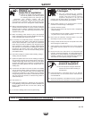
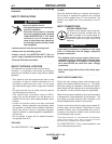
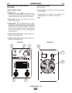
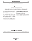
STICK WELDING (MMA)
Connect the electrode cable to the (+) terminal and the
work clamp to the (-) terminal. Insert the connector with
the key lining up with the keyway and rotate approxi-
mately 1/4 turn clockwise. Do not over tighten.
(See Figure A.1)
Work Clamp
Work Cable
Electrode
Holder
FIGURE A.1
WARNING
120V INPUT
The INVERTER ARC™ 120 is provided with a 120V
cable, 6.0ft.(1.8m) in length, with a 15Amp 5-15P plug
molded onto the cord.
The rated output of the INVERTER ARC™ 120 is
available when connected to a 20A branch circuit.
When connected to a branch circuit with lower ampac-
ity, lower welding current and duty cycle must be
used. An output guide is provided below. The values
are approximate and must be adjusted downward if
the fuse or circuit breaker trips off. Other loads on the
circuit and fuse/circuit breaker characteristics will
affect the available output. Do not exceed these weld-
ing conditions: (See Table A.1)
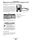
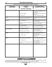
BRANCH CIRCUITS
Plug
Rating
15 Amp
15 Amp
Branch
Rating
15 Amp
20 Amp
20% Duty
Cycle
55A
70A
120V Input
Output Current
TABLE A.1
10% Duty
Cycle
60A
80A
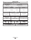
Factory Installed
Electrical Holder and Cable Assembly
Work Cable and Clamp
Strap Packet
Instruction Manual