


F-1
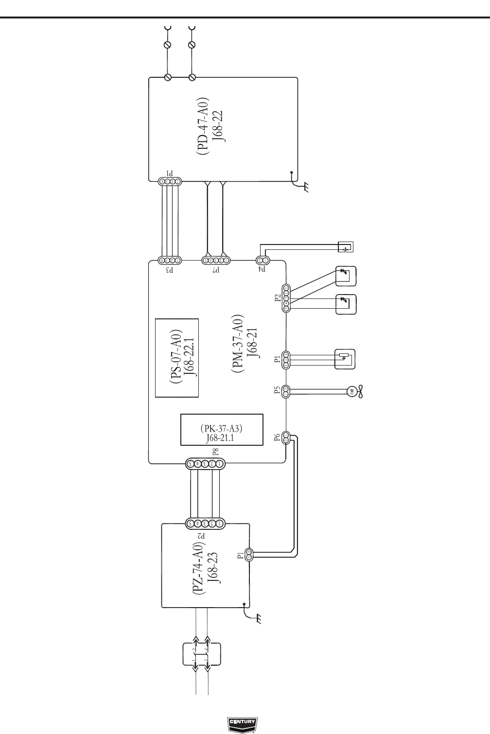
DIAGRAMS
F-1
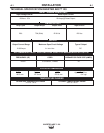
INVERTER ARC™ 120
NOTE: This diagram is for reference only. It may not be accurate for all machines covered by this manual. The specific diagram for a particular code is pasted inside
the machine on one of the enclosure panels. If the diagram is illegible, write to the Service Department for a replacement. Give the equipment code number.
OUTPUT
TERMINALS
MAIN
TRANSFORMER
FAN
FEEDBACK
CIRCUIT
C
O
N
T
R
O
L
M
O
D
U
L
E
GROUND
LEAD
ON / OFF
SWITCH
INPUT
POWER
LED
THERMAL
LED
OUTPUT
POTENTIOMETER
THERMOSTAT
OUTPUT
BOARD
INPUT
BOARD
DRIVE MODULE
RELAY
DC POWER
SUPPLY
GROUND
LEAD
MAIN
BOARD
INVERTER ARC 120 - WIRING DIAGRAM
WIRING DIAGRAM FOR CODE 11565