


WARNING; When using electric tools, basic safety pre-
cautions should be followed to reduce risk of fire, elec-
tric shock, and personal injury, including the following:
SAFETY INSTRUCTIONS
1) KEEP WORK AREA CLEAN - Cluttered areas and
benches invite injuries.
2) CONSIDER WORK AREA ENVIRONMENT - Do not
expose power tools to rain. Do not use power tools in
damp or wet locations. Keep work area well lit. Do not
use tools in the presence of flammable liquids or gases.
3) KEEP CHILDREN AWAY - All visitors should be kept
away from work areas.
4) STORE IDLE TOOLS - When not in use, tools should
be stored in dry, and high or locked-up places out of
reach of children.
5) DO NOT FORCE THE TOOL - It will do the job better
and safer at the rate for which it was intended.
6) USE THE RIGHT TOOL - Do not force small cutters
to do the job of heavy duty cutters. Always use a cutter
for its intended use only.
7) DRESS PROPERLY - Do not wear loose clothing or
jewelry as they can be caught in moving parts. Wear
protective hair covering to contain long hair.
8) USE SAFETY GLASSES - Also use face or dust
mask when operations are dusty. A vacuum cleaner or
dust extractor is strongly recommended.
9) SECURE THE TABLE - The router table should be
bolted down or clamped to a sturdy bench.
10) DO NOT OVERREACH - Keep proper footing and
balance at all times.
11) MAINTAIN CUTTERS WITH CARE - Keep cutters
sharp and clean for better and safer performance.
12) DISCONNECT ROUTER - When not in use and
before changing or adjusting cutters.
13) CHECK DAMAGED PARTS - Always inspect cut-
ters before use for signs of wear or damage. Do not use
cracked or broken cutters.
14) STAY ALERT - Use common sense. Do not operate
power tools when you are tired or under the influence of
drugs, alcohol or medication.
15) TAKE EXTRA CARE WHEN SWITCHING - Watch
what you are doing when turning the router on and off.
The NVR switch available as an optional item is recom-
mended to avoid the operator having to reach under the
table to operate the switch.
ASSEMBLY INSTRUCTIONS
Part numbers are shown in brackets, for example (12)
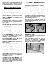
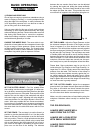
ASSEMBLE THE LEGS
The two rectangle frames which are the legs of the
router table can be mounted in two ways depending on
the type of router to be used. Smaller routers can be
used with the shorter side of the leg in the vertical posi-
tion, as shown in Fig.1. For larger routers the longer side
of the leg must be in the vertical position to lift the table
higher off the work bench, as shown in Fig.2.
If you have purchased the floorstand for this router table
the legs should be fitted with the shorter side vertical and
with the two holes at the bottom of the leg as shown in
the exploded view diagram Fig.15.
Attach the two Legs (2) to the table (1) using four
Countersunk screws M8x55mm (6), Washers M8 (8)
and Hex nuts M8 (7).
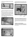
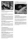
ASSEMBLE THE FENCE
i) Locate the Fence base (12), the Vertical supports (14),
and Wooden fences (11).
Insert Countersunk screw M6x25mm (25), through the
wooden fence, then throught the slot in the fence base
and then through the vertical clamp support. Secure it
with washer M6 (19) and knob female M6 (20).
Fig.1
Fig.2