


BASIC OPERATING
INSTRUCTIONS
1) EDGING AND PROFILING
One of the most common operations undertaken using a
router is Edging or Profiling, i.e. running a shaped cutter
along the edge of the workpiece. In many instances this
is for decorative purposes but it can also be to make a
joint or fitting such as a raised panel.
Using a router table for this type of work vastly reduces
the setting up time required and does away with many
awkward clamping devices. Router table users soon find
that having both hands free to control the workpiece,
rather than holding a machine, makes the task far more
comfortable and generally a lot safer.
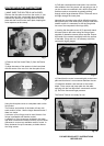
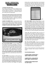
CHOOSE THE INSERT RING:- The router table is sup-
plied with an insert plate and two transparent insert rings
to give a range of cutter apertures. Always choose the
smallest possible aperture for safety. For example when
working with a cutter of 38mm diameter, use the outer
transparent ring which gives an aperture of 42mm.
SET THE CUTTER HEIGHT:- First fit a suitable cutter
after making sure the router is unplugged. It is often eas-
ier to do this by unscrewing the insert plate from the table
and lifting the router out of the table. Draw a profile of the
required cut onto the edge of the workpiece and adjust
the cutter height to match. Adjusting the cutter height is
made much easier if a fine height adjuster is fitted to the
router. With many models this now comes as standard,
but on others it is available as an accessory produced by
the router manufacturer. Having set the cutter height fit
the router back into the table and secure with the four
screws.
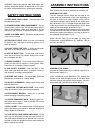
SET THE FENCE:- The next step is to set the fence in a
position to give the desired width of cut. Use the profile
drawn on the end of the workpiece to set the fence and
lock into position. There is a scale printed onto the table
to assist in rapid fence setting. When using a cutter fitted
with a guide bearing the fence should be set in line or
just in front of the edge of the bearing so that the work-
piece runs on the face of the bearing. The distance
between the two wooden fence faces can be adjusted
by undoing the knobs and sliding the clamp assembly
and fence along. The fence faces should be set so that
the edges just clear the cutter. This provides the maxi-
mum amount of support to the workpiece during the cut.
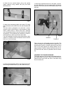
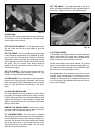
SET THE CLAMPS:- Adjust the Finger Pressure so that
the distance between the ends of the fingers and the
fence is between 2 to 5mm less than the width of the
workpiece. This will hold the workpiece securely against
the fence and prevent 'kick-back' during the cut. Next set
the left and right Top Clamps. The top clamps are made
of flexible plastic and should be set so that the distance
between the bottom of the clamp and the surface of the
table is between 1 to 3mm less than the thickness of the
workpiece. When the clamps are correctly set, the oper-
ator merely has to push the workpiece across the table.
Please Note: Some workpieces may be too big to fit
inside either the Top Clamps or the Finger Pressure, i.e.
larger than 70 x 80mm. Simply remove the clamp/finger
pressure from the table. The function of the clamps is
twofold; to hold the workpiece securely against the cut-
ter, whilst keeping the hands well away from it. When
using larger workpieces the increased weight will help to
keep it against the cutter and the danger of hands being
too near the cutter is greatly reduced.
SET THE CUTTER GUARD:- Adjust the transparent
guard so that it just clears the work piece and will deflect
any chips or dust which are thrown towards the opera-
tor. If possible connect a vacuum cleaner or dust extrac-
tor to the dust chute before commencing the cut.
Make a cut with a waste piece of wood before using the
workpiece. Mistakes cannot usually be rectified after-
wards.
THE GOLDEN RULES;
ALWAYS KEEP HANDS WELL
AWAY FROM THE CUTTER
ALWAYS USE A PUSH STICK
WITH SMALL WORKPIECES
ALWAYS FEED FROM RIGHT
TO LEFT ONLY
Fig. 11
Fig. 12