


ROUTER MOUNTING INSTRUCTIONS
i) MAKE SURE THE ROUTER IS UNPLUGGED.
Remove the face plate cover from the router ( If your
router does not have a removable face plate cover,
measure the spacing of the fixing holes in the face
plate and then mark out the insert plate, keeping the
cutter aperture as the centre).
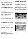
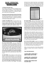
ii) Remove the Oval Insert Plate (3) from the Router
Table.
iii) Align the centre of the aperture in the insert plate
with the centre of the cut-out in the face plate cover.
Using the face plate cover as a template mark out the
fixing holes.
The number and position of the holes will vary with
each model of router. Use the larger diameter holes if
there is a choice.
A minimum of two fixings must be used, three or four
fixings is preferable with heavier routers.
A selection of fixing screws are included in this pack-
age which covers most common routers, but we cannot
guarantee to cover every available model of router. In
some instances it may be necesary to obtain alterna-
tive fixing screws.
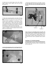
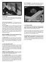
iv) Drill and countersink the insert plate. Use a drill bit
size suitable to the fixing screw you are going to use. If
you do not have a countersink tool, drill the fixing hole
and then make a countersink by partially drilling
through with a larger diameter drill bit. Take care not to
drill right through the insert plate.
Normally the mounting holes will be drilled through the
black plastic part of the insert plate, however with some
smaller routers it is necessary to drill the fixing holes
into one of the tranparent insert rings (4&5).
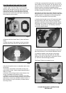
v) Leaving the face plate cover off (if removed) attach
the insert plate to the router using the fixing screws
supplied or alternative screws where required. Ensure
the heads of the screws are slightly below the surface
of the table. If they are not, it is necesary to drill the
countersink slightly deeper.
vi) Check that the router is secured tightly to the insert
plate and that there is no movement between the two.
vii) Install the desired cutter and set to the correct
depth. Fit the router and insert plate into the table,
securing with the four M6x16mm countersunk screws
(6). Re-fit the fence and finger pressure.
The Router Table is now ready for use.
PLEASE READ SAFETY INSTRUCTIONS
BEFORE USE.
Fig.7
Fig.8
Fig. 9
Fig. 10