


5. Appendix 13 1/7/2011 4:34 PM
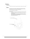
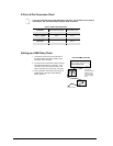
Cable Connectors
Cabling must have a male XLR connector on one end and a female XLR
connector on the other end.
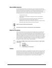
Do not allow contact between the common and the fixture’s chassis ground. Grounding
the common can cause a ground loop, and your fixture may perform erratically. Test
cables with an ohm meter to verify correct polarity and to make sure the pins are not
grounded or shorted to the shield or each other.
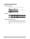
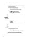
Setting the Starting Address
This DMX mode enables the use of a universal DMX controller device. Each fixture requires a
start address from 1~512. A fixture requiring one or more channels for control begins to read the
data on the channel indicated by the start address. For example, a fixture that uses six DMX
channels and was addressed to start on DMX channel 100, would read data from channels:
100, 101, 102, 103, 104, and 105. Choose start addresses so that the channels used do not
overlap, and note the start address selected for future reference.
If this is your first time addressing a fixture using the DMX control protocol, we suggest jumping
to the “Appendix” section and reading the heading “DMX Primer”. It contains very useful
information that will help you understand its use.
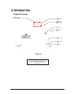
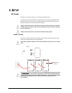
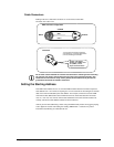
COMMON
DMX +
DMX -
INPUT
OUTPUT
1
3
2
1
3
2
1
3
2
120 ohm ¼ W resistor
between pin 2 (DMX -) and
pin 3 (DMX +) on the
output of the last fixture
To avoid signal transmission problems
and interference, it is always advisable to
connect a DMX signal terminator.
DMX connector configuration
Terminator