


Q-Spot™ 150-LED User Manual 11 9/22/2009 3:57 PM
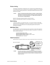
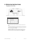
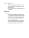
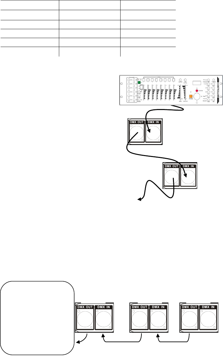
This drawing provides a
general illustration of the
DMX Input/Output panel of
a lighting fixture.
Universal DMX Controller
Continue the link
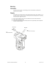
Often, the setup for Master-Slave
and Standalone operation requires
that the first fixture in the chain be
initialized for this purpose via either
settings in the control panel or DIP-
switches. Secondarily, the fixtures
that follow may also require a slave
setting. Please consult the
“Operating Instructions” section in
this manual for complete instructions
for this type of setup and
configuration.
Master
Slave
Slave
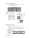
3-Pin to 5-Pin Conversion Chart
Note! If you use a controller with a 5 pin DMX output connector, you will need to use a 5 pin to 3 pin
adapter.
The chart below details a proper cable conversion:
3 PIN TO 5 PIN CONVERSION CHART
Conductor
3 Pin Female (output)
5 Pin Male (Input)
Ground/Shield
Pin 1
Pin 1
Data ( - ) signal
Pin 2
Pin 2
Data ( + ) signal
Pin 3
Pin 3
Do not use
Pin 4
Do not use
Pin 5
Setting up a DMX Serial Data
Link
1. Connect the (male) 3 pin connector side of
the DMX cable to the output (female) 3 pin
connector of the controller.
2. Connect the end of the cable coming from
the controller which will have a (female) 3
pin connector to the input connector of the
next fixture consisting of a (male) 3 pin
connector.
3. Then, proceed to connect from the output
as stated above to the input of the following
fixture and so on.
Master/Slave Fixture Linking
1. Connect the (male) 3 pin connector side of the DMX cable to the output (female) 3 pin connector
of the first fixture.
2. Connect the end of the cable coming from the first fixture which will have a (female) 3 pin
connector to the input connector of the next fixture consisting of a (male) 3 pin connector. Then,
proceed to connect from the output as stated above to the input of the following fixture and so on.