


Page 16 For technical questions, please call 1-800-444-3353. SKU 68886
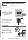
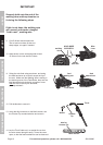
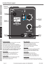
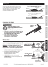
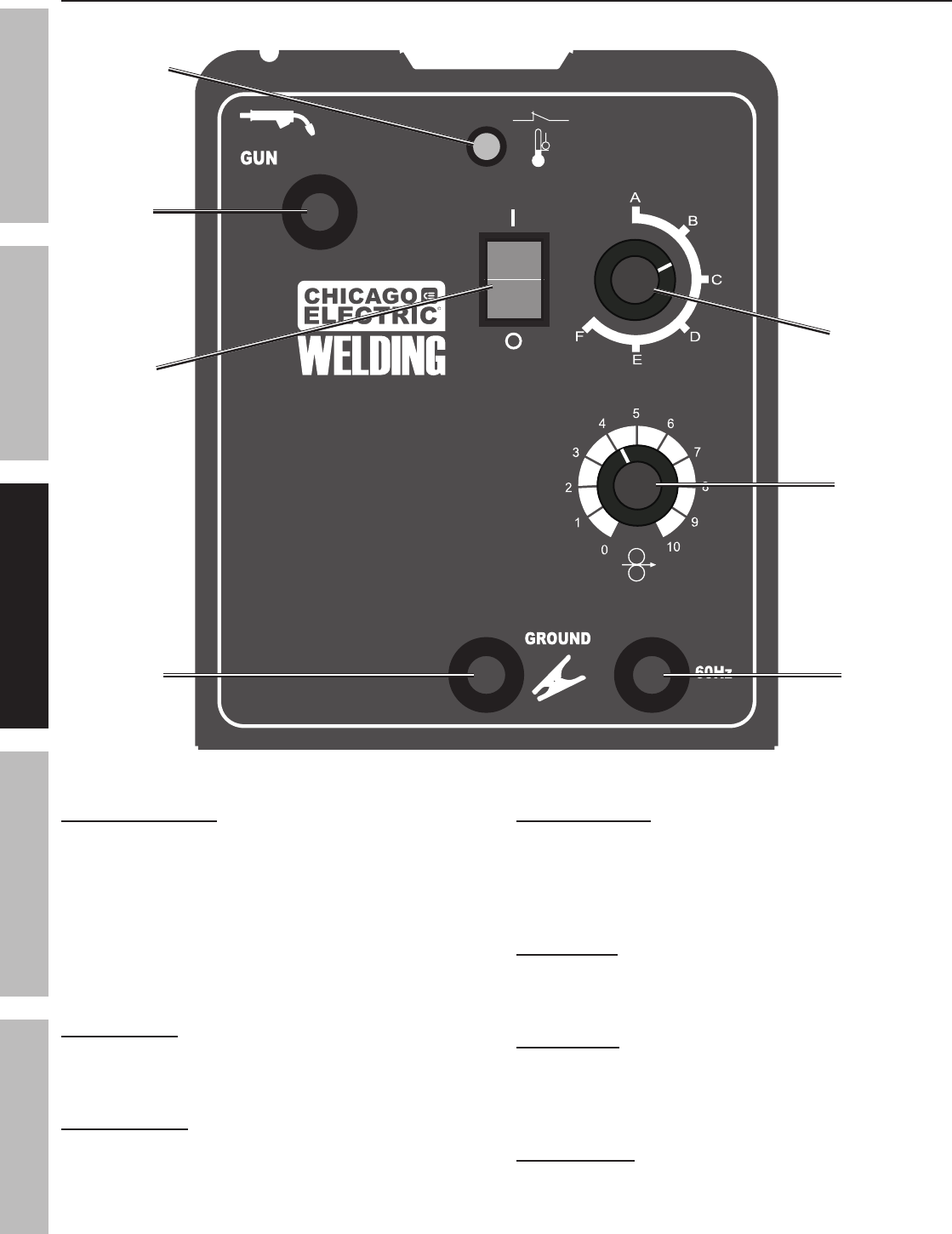
Control Panel Layout
Overload Indicator:
This lights up if duty cycle work period is exceeded,
resulting in overheating the welder.
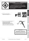
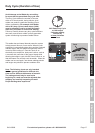
Rest the Torch on an electrically non-conductive,
heat-resistant surface, such as a concrete slab, well
clear of the ground clamp while allowing the welder
to cool with the Power Switch on, so the Fan can
help cool the welder. Once the welder cools enough
to be used again, use shorter welding periods and
longer rest periods to prevent needless wear.
Power Switch:
This turns on power to the welding Torch and
internal cooling fan. The welding Torch is
energized whenever the Power Switch is on.
Current Switch:
This controls the output amperage of the welder.
Adjust this according to the weld settings
chart to achieve a good weld.
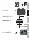
Wire Speed Dial:
This controls the speed that the welding wire
feeds out of the welding Torch and
adapts output amperage somewhat.
Adjust this according to the weld settings
chart to achieve a good weld.
Power Cord:
Plug the Power Cord into a properly grounded
240 V~ (at least 30 amp rating) outlet with
delayed action type circuit breaker or fuses.
Torch Cable:
The welding Torch connects here.
The wire and welding current feeds to
the weld through here. The welding Torch is
energized whenever the Power Switch is on.
Ground Cable:
This connects to the base metal to provide a good
connection for the current to travel back to the welder.
MIG 180
WIRE FEED WELDER
ITEM 68886
WIRE FEED SPEED
240V~
I
O
Wire
Speed
Dial
Torch
Cable
Ground
Cable
Power
Switch
Current
Switch
Overload
Indicator
Power
Cord
SAFETY MAINTENANCEBASIC WELDING WELDING TIPSSETUP