


Page 13For technical questions, please call 1-800-444-3353.SKU 68887
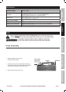
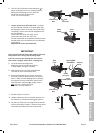
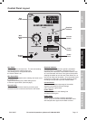
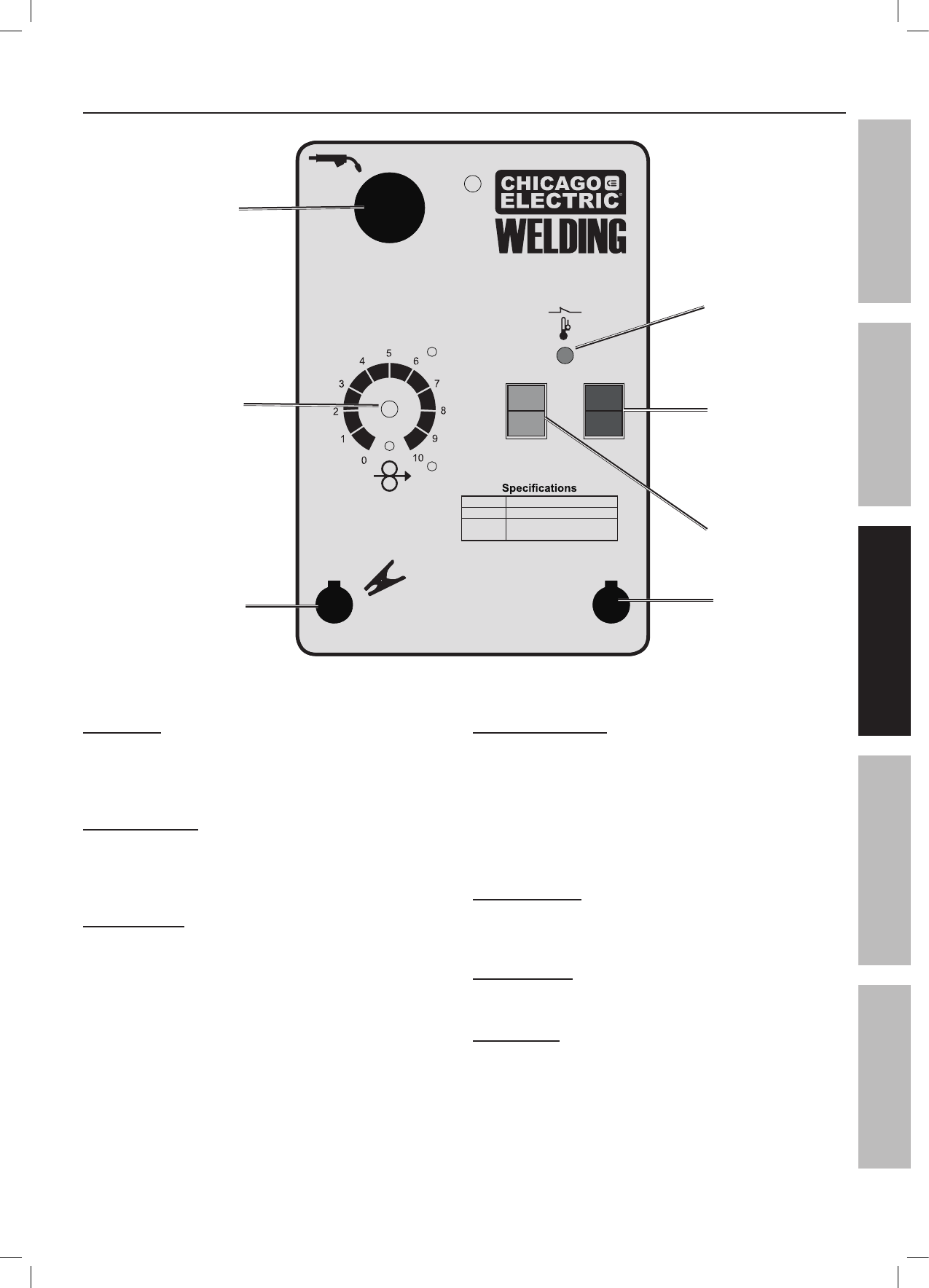
Control Panel Layout
ON MIN
OFF MAX
WIRE FEED SPEED
GUN
GROUND
120V~
60Hz
20A
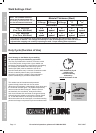
90 AMP FLUX WIRE WELDER
ITEM 68887
Wire .030″-.035″ Flux-core
Capacity XX Ga. – X/X″ Steel Plate
Cables
Electrode – X′
Ground Clamp – X′
Wire
Speed
Dial
Gun
Cable
Ground
Cable
Current
Switch
Power
Switch
Overload
Indicator
Power
Cord
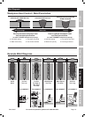
Gun Cable:
The welding Gun connects here. The wire and welding
current feeds to the weld through here.
The welding Gun is energized whenever
the Power Switch is on.
Wire Speed Dial:
This controls the speed that the welding wire feeds out of
the welding Gun.
Adjust this according to the weld settings chart
to achieve a good weld. (See next page.)
Ground Cable:
This connects to the base metal to provide a good
connection for the current to travel back to the welder.
Overload Indicator:
This lights up if duty cycle work period is exceeded
and the welder is overheated. Rest the Gun on an
electrically non-conductive, heat-resistant surface, such
as a concrete slab, well clear of the ground clamp while
allowing the welder to cool with the Power Switch on, so
the Fan can help cool the welder. Once the welder cools
enough to be used again, use shorter welding periods
and longer rest periods to prevent needless wear.
Current Switch:
This controls the output amperage of the welder.
Adjust this according to the weld settings
chart to achieve a good weld.
Power Switch:
This turns on power to the Welding Gun
and internal cooling fan.
Power Cord:
Plug the Power Cord into a properly grounded
120 V~ outlet, on at least a 20 amp dedicated circuit
with delayed action type circuit breaker or fuses.
SAFETYMAINTENANCE BASIC WELDINGWELDING TIPS SETUP