


SKU 93009
For technical questions, please call 1-800-444-3353
Page 8
3. To remove the blades, hold down the Spindle Lock (89) and insert the spanner’s pins into the two holes
on the Flange Nut (57) and remove it.
4. Remove, replace, or rearrange the blades and spacers as necessary. Important! All 6 Spacers (54
and 55) must be used at
all times, otherwise the blade will not be held securely. Also, Spacer (55) has
a step designed to hold Blade (56) securely, Blade (56) must be placed on this spacer’s step, if Blade
(56) is used.
5. Determine the desired spacing between the two blades. Be sure Clamping Flange (52) is in place on
the Spindle (43). Slide Inner Blade (53) onto the Spindle (43). Add as many Spacers (54 or 55) as
needed to create the desired spacing. Slide Outer Blade (56) onto the Spindle (43). Install any
remaining Spacers. Screw the Flange Nut (57) onto the Spindle (43) hand tight.
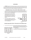
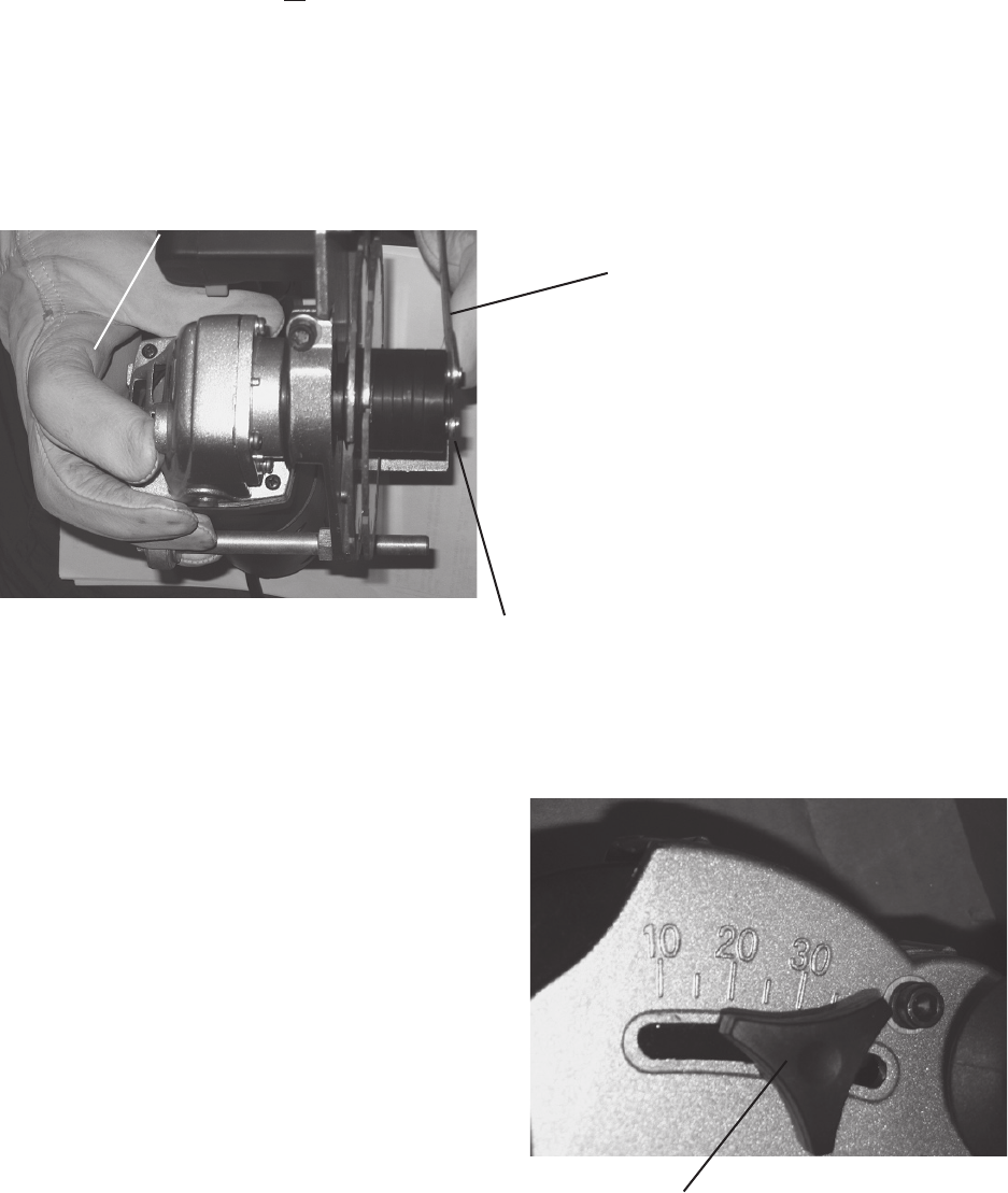
Refer to photo below
and drawing on page 12.
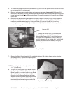
Spanner (92)
6. Press in the Spindle Lock (89) to prevent the
Spindle (43) from turning. Hold it in place while
tightening the Flange Nut (57). Using the Spanner
(92) tighten the Flange Nut (57) firmly in place by
turning it clockwise on the Spindle (43). Verify that all
spacers are installed and that blade(s) are tightly
secured in place.
Flange Nut (57)
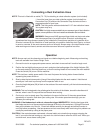
7. Replace the Blade Guard Assembly (59) and Height Adjuster (58). Tighten these in place using the
Screws (63 and 64). Replace the Depth Adjuster
Handle (60).
NOTE: The cutting depth can be adjusted from .4” to
1.18” (10 to 30 mm).
8. To adjust the cutting depth of the blades, loosen
the Depth Adjuster Handle (60), and move the
Blade assembly up or down relative to the Blade
Guard (59). A gauge is inscribed on the Blade
Guard for your reference. Retighten the Depth
Adjuster Handle (60) before beginning work. Be
sure to test the depth and width of the cut on a
test piece before commencing work on the final
work material.
Spindle Lock (89)
Depth Adjuster Handle (60)