


SKU 93853 For technical questions, please call 1-800-444-3353 PAGE 13
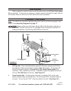
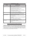
Variable Speed Control (72): 3. The Demolition Hammer is equipped with a
Variable Speed Control Dial. The impact rate (BPM) and rotating speed (RPM)
can be varied according to the type of work being performed by setting the
Variable Speed Control Dial to the selected setting: 1-2-3-4-5-6 (“1” Being the
lowest. “6” Being the highest.) The Variable Speed Control Dial may be
adjusted while the Motor is running with the tool free from work, allowing the
operator to adjust the impact rate and rotating speed according to the actual
application.
(See Figure E.)
Auxiliary Handle (104A) and Knob (105): 4. The Demolition Hammer must
be supported with the Auxiliary Handle, which can be swiveled 360 degrees.
To reposition and/or swivel the Auxiliary Handle, loosen the Knob. Move the
Auxiliary Handle to the desired position along the barrel of the tool and rmly
retighten the Knob. (See Figure E.)
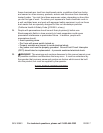
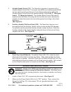
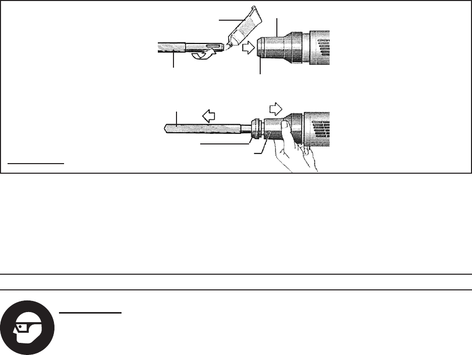
FIGURE F
SLIDER (4)
FRONT CAP
(1)
OIL OR GREASE
(NOT INCLUDED)
CHISEL
(106, 107)
CHISEL
(106, 107)
SLIDER (4)
FRONT CAP (1)
5. Front Cap (1) and Slider (4): To install a Chisel (106, 107), clean the insert
shank end of the chisel to remove any debris. Then, lightly grease the shank
with a light oil or grease. Insert the Chisel into the Slider through the Front Cap,
while twisting and pushing inward until the Chisel locks into place. Pull outward
on the Chisel to make sure it is locked into the Slider. (See Figure F.)
OPERATING INSTRUCTIONS
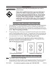
WARNING! Always wear ANSI-approved safety impact eye glasses and
a full face shield when using the Demolition Hammer. Also wear heavy
duty steel-toe boots, hearing protection, dust mask or respirator, and heavy
duty work gloves.
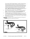
Install a Chisel (106, 107) as previously discussed. 1. (See Figure F.)
Make sure the Power Switch (66) is in its “OFF” position. Then, connect the 2.
Power Cord & Plug (70) to the nearest 120 volt, grounded electrical outlet.
(See Figure E.)
REV10d