


Page 10SKU 97743 For technical questions, please call 1-800-444-3353.
Tool Set Up
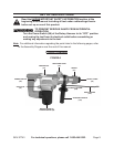
Adjusting The Auxiliary Handle:
The Auxiliary Handle (107) can be 1.
placed in a variety of positions.
(See Figure A.)
To rotate the Auxiliary Handle 2.
(107), turn the Auxiliary Handle
counterclockwise to loosen the band
and Foursquare Bolt (111). Once
loosened, turn the Auxiliary Handle
to the desired position. Then turn the
Handle clockwise to secure in place.
(See Figure A.)
Using The Depth Gauge:
The Depth Gauge (106) can only be 1.
used if the Auxiliary Handle (107) is
positioned on either side or the top of
the Rotary Hammer. The body of the
Hammer will interfere with the Depth
Gauge if the Handle is in the bottom
position. (See Figure A.)
2.
turning the Handle counterclockwise.
(See Figure A.)
Once the Auxiliary Handle (107) is 3.
Handle Holder (108) until the hole in
the Handle is fully open.
(See Figure A.)
Slide the Depth Gauge (106) in to the 4.
desired length. The tip of the Depth
Gauge on the front of the Hammer
should be the desired depth of the
hole to be drilled. The depth is from
the tip of the Drill Bit to the tip of the
Depth Gauge.
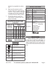
For example; for a 2” deep hole,
measure 2” back from the tip of the
Drill Bit. Then position the front tip
of the Depth Gauge at that spot.
(See Figure A.)
After the Depth Gauge (106) is 5.
placed in the desired position, turn
the Auxiliary Handle (107) clockwise
until tight. The Depth Gauge should
be securely in position and should not
move. (See Figure A.)
Changing The Settings:
The Rotary Hammer has a Switching 1.
Knob (24) and a Selector (91) which
hammer drilling, or chiseling.
(See Figure A.)
WARNING! 2. Move the Switching
Knob (24) and Selector (91)
only when the Motor is stopped.
Attempting to move the Switching
Knob or Selector while the Motor
is engaged will result in abrupt Bit
rotation and can cause serious
damage.
(See Figure A.)
CAUTION: 3. When moving the
Switching Knob (24) and Main
Handle (91), make sure both actively
“click” into the desired position. If not
actively engaged, the Knob or Handle
could slip out of position resulting in
unexpected tool performance.
(See Figure A.)
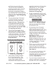
The front Switching Knob (24) has on 4.
one side a symbol of a Hammer and
a Drill. On the other side is a symbol
(See Figure A.)
The Main Handle (91) can be pointed 5.
either left or right. There are symbols
for a Hammer and a Drill on the left