


96 4021196 Rev C
Front Panel LED Status Indicator Functions
Front Panel LED Status Indicator Functions
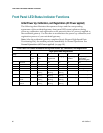
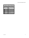
Initial Power Up, Calibration, and Registration (AC Power applied)
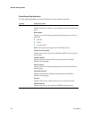
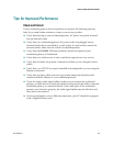
The following chart illustrates the sequence of steps and the corresponding
appearance of the residential gateway front panel LED status indicators during
power up, calibration, and registration on the network when AC power is applied to
the residential gateway. Use this chart to troubleshoot the power up, calibration, and
registration process of your residential gateway.
Note: After the residential gateway completes Step 6 (Request High-Speed Data
Provisioning File), the modem proceeds immediately to Normal Operations. See
Normal Operations (AC Power applied) (on page 98).
Front Panel LED Status Indicators During Initial Power Up, Calibration, and Registration
High Speed Data Registration
Step:
1
2
3
4
5
6
Front Panel Indicator
Self
Test
Downstream
Scan
Downstream
Signal Lock
Ranging
Requesting IP
Address
Request High
Speed Data
Provisioning File
1
POWER
On
On
On
On
On
On
2
DS
On
Blinking
On
On
On
On
3
US
On
Off
Off
Blinking
On
On
4
ONLINE
On
Off
Off
Off
Off
Blinking
5
ETHERNET1-4
On
On or
Blinking
On or
Blinking
On or
Blinking
On or Blinking
On or Blinking
6
USB
On
On or
Blinking
On or
Blinking
On or
Blinking
On or Blinking
On or Blinking
7
WIRELESS
LINK
Off
On or
Blinking
On or
Blinking
On or
Blinking
On or Blinking
On or Blinking
8
WIRELESS
SETUP
Off
On or
Blinking
On or
Blinking
On or
Blinking
On or Blinking
On or Blinking