


RLL233 Issue 4 Aug 2007
18
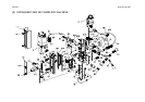
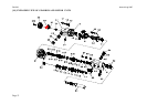
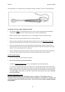
[14] REPLACEMENT OF MOTOR SUPPLY CABLE.
TO REMOVE OLD CABLE AND CHAIN
Ensure that the machine is disconnected from any source of power. Failure to do so may
result in personal injury.
• Remove screws #73 and withdraw the control unit from the housing.
• Disconnect the nine-pin cable connector from the control panel
• Remove the motor supply cable leads (8 and 9) from the terminal block by unfastening
the screws.
• Release the cable clip inside the housing cavity.
• Rotate the capstan to raise the motor & gearbox assembly to the maximum up position
(ensure that cutter retaining screws #11 do not foul arbor support bracket #7).
• Remove the cable chain anchor screw #68 and release the cable chain #29.
• Remove capstan retaining screw #49 and withdraw capstan assembly #55
• Withdraw the motor and slide assembly from the housing.
• Remove screws #18 and separate motor and slide.
• Remove the cable from the cable chain.
• Remove screws #67 and cable cover #66.
• Release the cable from the cable clip and terminal blocks.
TO REFIT NEW CABLE.
• Reverse the above procedure.
• Now test the machine as described below:
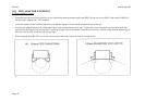
Earth Continuity Test
A current of 25A having a no load voltage of 6v is passed between the earth contact of the
mains plug and the frame of the machine. With the standard 3m length of cable the
resistance shall not exceed 0.3 ohms. If this figure is exceeded, a faulty earth connection
has been made. It must be found and rectified.
Insulation Resistance Test
With the magnet switch in the ON position, apply a voltage of 1.5kv between the live
connection on the mains plug and the frame of the machine for a duration of 7 seconds. The
reading obtained should not fall below infinity. Should a fault be indicated it must be found
and rectified.
REPLACEMENT OF MAINS SUPPLY CABLES RD271 and RD272