


RLL233 Issue 4 Aug 2007
19
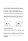
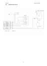
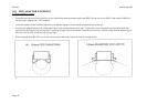
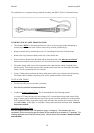
The replacement is a complete factory produced assembly, and RD272 (230v) is illustrated below.
TO REMOVE OLD CABLE FROM MACHINE
• The machine MUST be disconnected from any source of power supply before attempting to
conduct any maintenance work. Failure to do so may result in personal injury.
• Remove control unit by unfastening screws #73 and lifting the unit clear of the housing.
• Remove the 9-pin connector block on the rear of the control unit.
• Wires which are fastened into the block and not from the mains cable must not be released.
Unfasten the terminal screws marked L & N and release the mains cable wires.
• The mains supply cable is now only connected to the earth terminal, which is located in the
housing cavity. Release the top nut of the assembly and extract the wire from under the saddle
clamp. All wire connections are now released.
• Using a 27mm spanner unfasten the mains cable gland, which screws directly into the housing.
The whole cable assembly comprising of the sleeve, gland and cable will be released.
TO FIT A NEW CABLE
• To fit a new cable, reverse the above procedure.
• Now test the machine as described below:
• Conduct an Earth Continuity Test. This is accomplished in the following manner:
A current of 25 amps having a no load voltage of 6V is passed between the earth contact of the
plug (or mains supply earth conductor) and in turn to any accessible metallic part of the machine.
With a standard 3-metre long mains supply cable affixed to the machine the resistance shall not
exceed 0.3 ohms. If this figure is exceeded, a faulty earth connection has been made. It must be
found and rectified.
Insulation Resistance Test
With the magnet switch in the ON position, apply a voltage of 1.5kv between the live
connection on the mains plug and the frame of the machine for a duration of 7 seconds. The
reading obtained should not fall below infinity. Should a fault be indicated it must be found
and rectified.
Oilite Bush
RD3192
(3 required)