


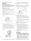
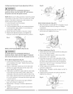
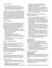
Cutting head downward travel adjustment (FIG. L)
IA WARNINGI
To avoid injury from unexpected starting or
electrical shock, turn the switch OFF and remove
the power cord from the power source.
NOTE: Before each cutting operation, check the position
of the blade to make sure it does not contact any metal
surface. If the blade contacts any metal surface, the
depth of trave! must be adjusted.
1. Lower the blade as far as possible.
2. Loosen the Iocknut (3).
3. Turn the adjustment balt (4) out (counterclockwise)
to decrease the cutting depth or in (clockwise) to
increase the cutting depth.
4. Rotate the blade manually to check for contacL
5. Repeat until adjusted properly, and tighten the
!ocknut to secure the adjustment bolt into position.
Fig. L
4
3
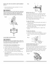
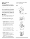
BEVEL STOP ADJUSTMENT (FIG. M & N)
WARNINGI
To avoid injury from unexpected starting or
electrical shock, make sure the trigger is released
and remove the power cord from the power source.
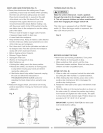
90°(0 °) Bevel adjustment (Fig. M)
1. Loosen bevel lock handle (1) and tilt the cutting
arm completely to the right. Tighten the bevel lock
handle. Lower blade.
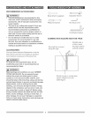
2. Place a combination square (2) on the miter table
with the rule against the table and the hee! of the
square against the saw blade.
3. If the blade is not 900(0°) square with the miter table,
loosen the bevel lock handle, tilt the cutting head
completely to the left, loosen the jamb nut (4) on the
bevel angle adjustment bait (3) and adjust the bolt (3)
in or out to increase or decrease the bevel angle with
a 10 mm wrench.
4. Tilt the cutting arm to back to the right at 900(0°)
bevel and recheck for alignment.
5. Repeat steps 1 through 4 if further adjustment is
needed.
6. Tighten bevel lock handle and jamb nut (4) when
alignment is achieved.
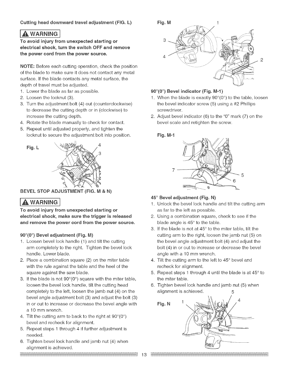
Fig. M
3
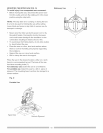
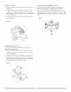
90°(0 °) Bevel indicator (Fig. M-I )
7 2
1. When the blade is exactly 900(0°) to the table, loosen
the bevel indicator screw (5) using a #2 Phi!lips
screwdriver.
2. Adjust bevel indicator (6) to the "0" mark (7) on the
bevel scale and retighten the screw.
Fig. M-l
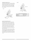
45° Bevel adjustment (Fig. N)
1. Unlock the beve! lock handle and tilt the cutting arm
as far to the left as possible.
2. Using a combination square, check to see if the
blade angle is 45° to the table.
3. If the blade is not at 45 ° to the miter table, tilt the
cutting arm to the right, loosen the jamb nut (5) on
the bevel angle adjustment bolt (4) and adjust the
bolt (4) in or out to increase or decrease the bevel
angle with a 10 mm wrench.
4. Tilt the cutting arm to the left to 45° bevel and
recheck for alignment.
5. Repeat steps 1 through 4 until the blade is at 45° to
the miter table.
6. Tighten bevel lock handle and jamb nut (5) when
alignment isachieved.
Fig. N
5
13