


ALiGNiNGTHELASER BEAM
[A WARNING[
For your own safety, never connect the plug to
power source outlet unti[ all the adjustment steps
are complete and you have read and understood the
safety and operational instructions.
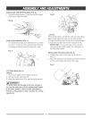
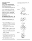
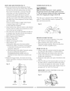
(1)_ Start with the set screw on the left side of the
laser assembly, then with the front set screw on the
right side of the laser assembly.
Fig. N-1
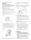
The laser beam must always be correctly aligned with
the blade to ensure straight, even cutting.
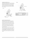
Your tool is equipped with the Laser Trac® cutting
guide using Class ilia laser beams. The laser beam wilI
enable to preview the saw blade path on the stock to
be cut before starting the miter saw. This laser guide is
powered by the transformed alternating current supply
directly through the power lea& The saw must be
connected to the power source and the laser on/off
switch must be turned on for the laser line to show.
wARN NeI
AVOID DIRECT EYE CONTACT
Loser radiated when [aser guide is turned oil. Avoid
direct eye contact° Always un-piug the miter saw
from power source before making any adjustments.
Laser " 'i
Switch i_
NOTE: All the adjustments for the operation of this
machine have been completed at the factory. Due to
normal wear and use, some occasional readjustments
may be necessary.
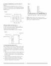
A. Check Loser Beam Alignment.
1. Mark a 90° straight line across a board to serve as a
"pattern line" to test laser alignment. Lay the board
on the miter table.
2. Plug saw into outlet and turn on the laser beam and
line it up with the pattern line.
3. Lower saw blade to pattern line and if blade is
not flush with the pattern line, adjust as follows in
procedures (B).
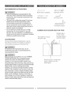
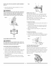
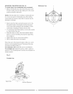
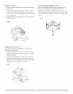
B. Adjusting the Angle of the Laser Trac®(Fig. N-2)
1. Turn the laser element (1) in the desired direction
to adjust the laser angle. NOTE: Do not adjust the
laser more than _Aturn in either direction as this may
damage the laser. There are two flat sides on the
laser element where you can position an adjustable
wrench for your adjustment.
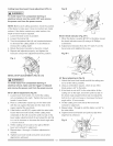
C. Aligning The Laser Beam
1. Loosen only Y2turn at a time the three set screws (1).
2. Adjust laser by turning the left side set screw
clockwise to shift the laser line to the right. To shift
the laser line to the left, turn the right side set screws
_/2turn at a time.
3. Once alignment of the laser isachieved,
tighten only Y2turn at a time the three set screws
Fig. N-2
Left Side View
Right Side View
14