


14 15
14 15
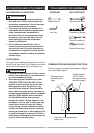
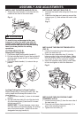
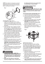
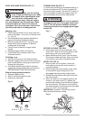
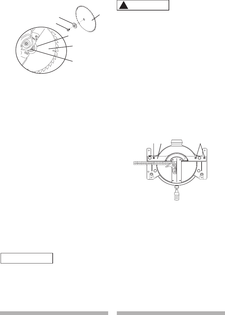
Installing Blade (Fig. G, H, I)
1. Install a 10 in. blade with a 5/8 in. arbor
making sure the rotation arrow on the blade
matches the clockwise rotation arrow on the
upper guard, and the blade teeth are pointing
downward.
2. Place the blade collar (6) against the blade
and on the arbor. Thread the arbor bolt (4)
onto the arbor in a counterclockwise direction.
(Fig. G) IMPORTANT: Make sure the flats of
the blade collars are engaged with the flats on
the arbor shaft. Also, the flat side of the blade
collar must be placed against the blade.
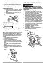
3. Place the blade wrench on the arbor bolt.
4. Press the arbor lock (5), holding it in firmly
while turning the blade counterclockwise.
When arbor lock engages, continue to press it
in while tightening the arbor bolt securely.
(Fig. H)
5. Rotate the cover plate (3) back to its original
position until the slot in the cover plate
engages with the cover plate screw (2). While
holding the lower blade guard, tighten the
screw with a Phillips screwdriver. (Fig. G)
NOTE: The lower blade guard must be raised
to the upright position to access the cover
plate screw.
6. Lower the blade guard (1) and verify that the
operation of the guard does not bind or stick.
7. Be sure the arbor lock is released so the
blade turns freely.
● To avoid injury, never use the saw
without the cover plate secure in place. It
keeps the arbor bolt from falling out if it
accidentally loosens, and helps prevent
the spinning blade from coming off the
saw.
● Make sure the collars are clean and
properly arranged. Lower the blade into
WARNING
!
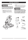
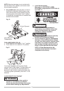
MITER SCALE (FIG. K)
The miter scale assists the user in setting
the desired miter angles from 45° left to 45°
right. The miter saw table has nine of the most
common angle setttings with positive stops at
0°, 15°, 22.5°, 31.6°, and 45°. These positive
stops position the blade at the desired angle
quickly and accurately.
To Adjust the Angle:
1. Unlock the miter table by turning the miter
handle (1) counterclockwise.
2. Press down the positive stop locking lever (2)
while holding the miter handle, and rotate the
table left or right to the desired angle.
3. Release positive stop locking lever. Tighten
miter handle.
4. If the desired angle is one of the nine positive
stops, release the positive stop locking lever,
making sure the lever snaps into position,
To avoid injury from an accidental start, make
sure the switch is in the OFF position and the
plug is not connected to the power source
outlet.
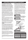
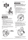
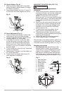
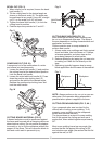
ADJUSTING FENCE SQUARENESS (FIG. J)
1. Loosen the three fence locking bolts (1).
2. Lower the cutting arm and lock in position.
3. Using a square, lay the heel of the square
against the blade, and the rule agaist the
fence(2) as shown.
Check to see if the fence is 90° to the blade.
4. If not, adjust fence 90° to the blade and
tighten the fence locking bolts.
CAUTION: If the saw has not been used
recently, recheck blade squareness to the
fence and readjust if needed.
5. After fence has been aligned, using a scrap
piece of wood, make a cut at 90
o
then
check squareness on the piece. Readjust if
necessary.
Fig. J
NOTE: Pay attention to the pieces removed,
noting their position and direction they face.
Wipe the blade collars clean of any sawdust
before installing the new blade.
Fig. I
6
7
8
8
6
7
the table and check for any contact with
the metal base or the turn table.
ADJUSTMENT INSTRUCTIONS
1
1
2
WARNING
!