


14 15
14 15
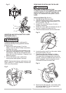
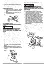
5. If the miter angle desired is not one of the
nine positive stops, simply lock the miter
table into position by turning the miter handle
in the clockwise direction.
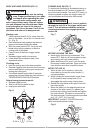
To Adjust the Indicator:
(1) Adjust the indicator (3) to the 0 ° mark on
the miter scale (4) to position the miter
table.
(2) Release positive stop locking lever (2).
Tighten miter handle.
Fig. K
and then secure by tightening the miter
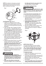
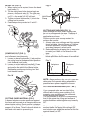
CUTTING ARM TRAVEL
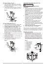
Cutting Arm Downward Travel Adjustment
(Fig. L)
To avoid injury from unexpected starting
or electrical shock, turn the switch OFF
and remove the power cord from the power
source.
NOTE
: Before each cutting operation, check the
position of the blade to make sure it does not
contact any metal surface. If the blade contacts
any metal surface, the depth of travel must be
adjusted.
1. Lower the blade as far as possible.
2. Loosen the locknut (3).
3. Turn the adjustment bolt (4) out
(counterclockwise) to decrease the cutting
depth or in (clockwise) to increase the cutting
depth.
4. Carefully rotate the blade manually to check
for contact. Avoid touching blade points or
edges.
5. Repeat until adjusted properly, and tighten
the locknut to secure the adjustment bolt into
position.
Fig. L
1
2
4
3
3
4
WARNING
!
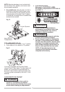
BEVEL STOP ADJUSTMENT (FIG. M, N, O)
To avoid injury from unexpected starting
or electrical shock, make sure the trigger is
released and remove the power cord from the
power source.
WARNING
!
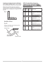
90° Bevel Adjustment (Fig. M)
1. Loosen bevel lock handle (1) and tilt the
cutting arm completely to the right. Tighten
the bevel lock handle. Lower blade.
2. Place a combination square (2) on the miter
table with the rule against the table and the
heel of the square against the saw blade.
3. If the blade is not 90° square with the miter
table, loosen the bevel lock handle, tilt the
cutting head completely to the left, loosen
the locknut (4) on the bevel angle adjustment
bolt (3) and use a 13 mm wrench to adjust
the bolt (3) in or out to increase or decrease
the bevel angle.
4. Tilt the cutting arm to back to the right at 90°
bevel and recheck for alignment.
5. Repeat steps 1 through 4 if further
adjustment is needed.
6. Tighten bevel lock handle and locknut (4)
when alignment is achieved.
Fig. M
3
2
4
1