


9
ASSEMBLY INSTRUCTIONS
A
10mm and 13mm open-end wrench (included) is
required for assembly of the Tool Rest Assemblies and
the Spark Arrestor Assemblies.
• DO NOT assemble the Bench Grinder until you are
sure the tool IS NOT plugged in.
• DO NOT assemble the Bench Grinder until you are
sure the power switch is in the “OFF” position.
• DO NOT assemble the Bench Grinder until you are
sure the grinding wheels are firmly tightened to the
Bench Grinder.
TOOL RESTS (Figs. D and E)
The Bench Grinder is provided with two dif
ferent Tool
Rest assemblies.
The Left Side Tool Rest is entirely flat.
The Right Side Tool Rest is also flat, but has an acces-
sory plate for sharpening drill bits.
1. Remove both Tool Rest Assemblies from the plastic
bags and check to see that you have the following:
Left Side Tool Rest
Left Side Tool Rest Support
Right Side Tool Rest
Right Side Tool Rest Support Drill Bit Sharpening
Plate M8 Flat Washer (qty. 6)
M8 x 12mm Hex head screw (qty. 4)
Adjustment Knob (qty. 2)
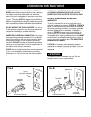
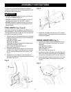
2. Assemble the Tool Rest Supports (A) to the inside
surface of the Wheel Covers (B) with the flat wash-
ers (C) and hex head screws (D) as shown. See
Fig. D.
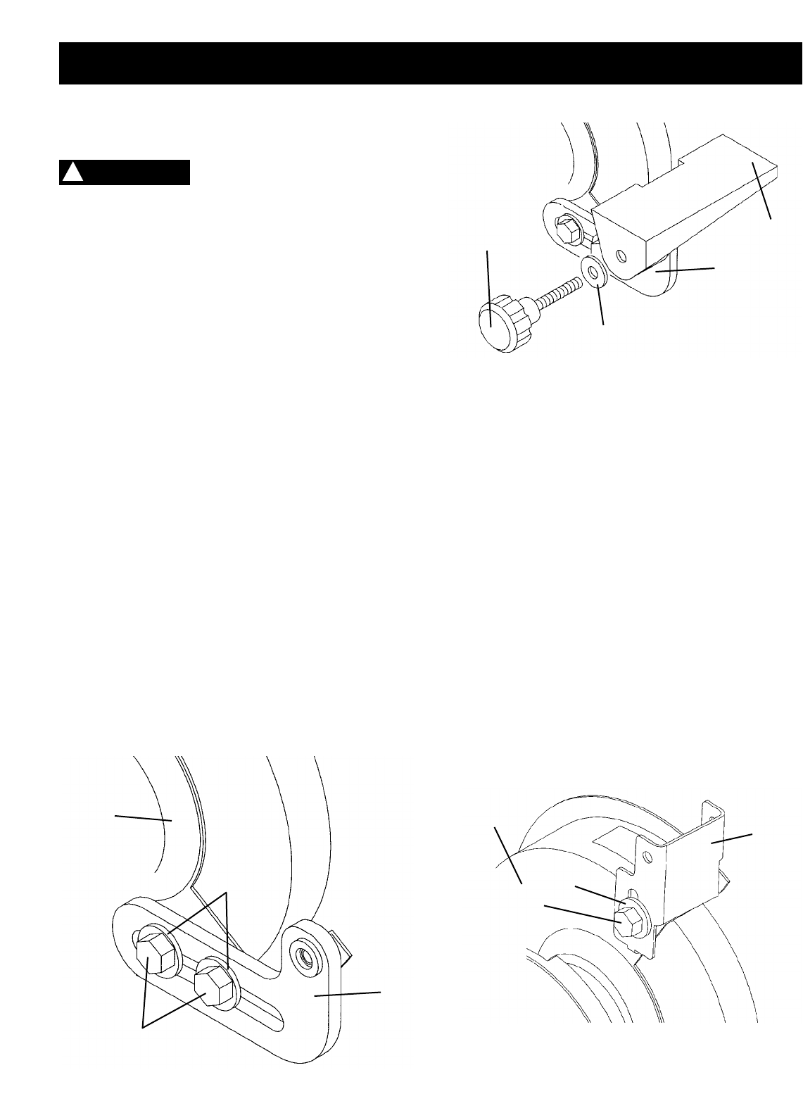
3. Assemble the Tool Rests (E) to the Supports (F)
with the flat washers (G) and Adjustment Knobs (H)
as shown. See Fig. E.
Fig. E
Fig. D
4. Adjust the Tool Rests until they are 1/16” from the
grinding wheels. Firmly tighten the hex head screws
holding the supports.
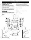
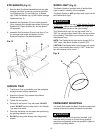
SPARK ARRESTORS (Fig. F)
1. Remove both Spark Arrestor Assemblies from the
plastic bags and check to see that you have the
following:
Left Side Spark Arrestor
Right Side Spark Arrestor
M6 Flat Washer (2)
M6 X 6mm Hex head screw (2)
2. Assemble the Spark Arrestors (A) to the inside sur-
face of the Wheel Covers (B) with the flat washers
(C) and hex head screws (D) as shown. See Fig. F.
3. Adjust the Spark Arrestors until they are 1/16" from
the grinding wheels. Firmly tighten the hex head
screws.
Fig. F
WARNING
!
D
C
B
A
E
F
G
H
A
C
D
B