


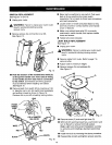

SWITCH REPLACEMENT
See Figures 15 and 16.
• Unplug your router,
_k WARNING: Failure to unplug your router could
result in accidental starting causing
serious injury.
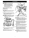
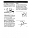
• Remove screws (A) and handle cover (B).
See Figure 15.
B
c
.15
• Note the location of the molded bend relief (C)
on the power handle cord. Also note all wiring
in the handle and how each lead is connected
to the switch. Connections and wiring position
must be identical when installing new switch.
See Figure 15.
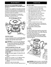
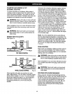
• Remove leads from switch (D) by inserting a 1/32
in. diameter nail or pin intoswitch lead receptacle
and pulling on lead as shown in Figure 16.
Remove nail or pin with a twisting, pulling motion.
LEAD
• Make lead connections to new switch. Push each
lead as far as possible into proper switch
receptacle. Pull on leads to check lead connections
with lead receptacles.
• Locate switch in handle and place leads so they
won't be pinched or contact screws when handle
cover is replaced.
• Make sure molded bend relief (C) is correctly
positioned in switch handle, then replace handle
cover and screws.
• Tighten all screws securely.
LIGHT BULB REPLACEMENT
See Figure 17.
• Unplug your router.
,_k WARNING: Failure to unplug your router could
result in accidental starting causing serious
injury.
• Remove cutter from router. Refer to page 7 to
remove cutter.
• Adjust router to maximum height.
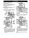
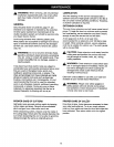
• Remove screws (A) and subbase (B).
See Figure 17.
c
D i B
i E
POWER
HANDLE
CORD
WORK
LIGHT
WHITE
RED
BLACK
1/32in. DIAMETER
NAILORPIN
RED
Fig. 16
17
• Remove screw (C) and work light lens (D).
• With bulb (El pointing toward you, push bulb in and
turn to the left to remove from bulb socket.
Note: Light bulb removal and installation is similar
to removing and installing a standard automotive
bulb.
• Install new bulb by reversing the above procedure.
• Reassemble all parts and tighten screws securely.
15