


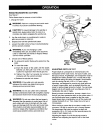

TO SWITCH FROM PLUNGE BASE TO FIXED BASE
OR D-HANDLE BASE
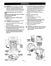
See Figures 4, 5, and 6.
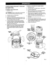
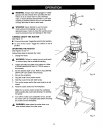
TO REMOVE THE PLUNGE BASE
1. Unplug the router.
• 1, WARNING: Failure to unplug the tool could result
in accidental starting causingserious injury.
2.
3.
4.
Place the router on a flat sudace.
Loosenthe locking knob.
Depress and hold the gold spindle lock button. The
gold spindle lock button will not depress fully unless
it is in line with the hole in the collet.
5. If the gold spindle lock button does not depress
fully, turn the collet nut while depressing the gold
spindle lock button. As they align, the gold spindle
lock button will depress fully.
6. Remove the motor housing from the plunge base.
NOTE: As the motor is being removed from the
base, the gold spindle lock button has to be de-
pressed until it clears the opening beneath the
base.
LOCKING
KNOB X
GOLD
__uTTPINDLE LOCK
ON
Fig. 4
11
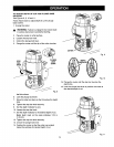
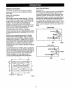
TO INSTALL THE FIXED OR D-HANDLE BASE
1. Unplugthe router,
2. Place the fixed or D-handle base on a flat surface.
3. Loosenthe lockingarm.
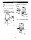
4. Align the indicator arrow on the depth adjustment
ringwith the indicatorpoint on the base.
5. Align the groove in the motorhousingwiththe tab
inside of the base. NOTE: The tab is located on the
inside of the base in line with the handle.
6. Depress and hold the gold spindle lockbutton on
the motor.
7. Slide the motor housing into the base.
8. Turn the depth adjusting ring counterclockwise ur_til
the gold spindle lock snaps out as it clears the rear
window, just below the locking arm.
9. Tighten the locking arm.
GROOVEIN_
MOTOR....._
HOUSING_
DEPTH
ADJUSTMENT
RING
TABINSIDE THE
BASE
Fig. 5
INDICATOR
ARROW
RING
Fig. 6