


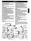
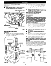
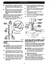
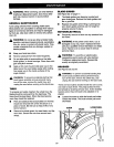

Check the position of the blade on the lower tire.
The blade should be completely on the tire. If
not, adjust the tracking until the blade is on both
tires.
• Rotate the upper wheel by hand in a clockwise
direction for a few more turns. Make sure the
blade stays in the same location on the tires.
Readjust if necessary, until blade is tracking
properly.
Note: The 1/8 in. blade may not track propedy in the
center of the wheel. It may be better to track this
blade on the back half of the upper wheel.
• Replace hex key in holder located inside of the
front cover. Close front cover.
• Rotate angle adjustment knob to tilt the table up
or down to align table 90" to blade (0" position).
Tighten the table lock knob.
• Using the 118in. hex key, adjust the zero stop
set screw until the set screw just touches the
frame.
Check squareness of table to blade. Make
readjustments if necessary.
Loosen screw on scale indicator and align red
mark to zero on scale. See Figure 7, page 12.
Tighten all screws securely.
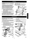
BLADEGUIDE
KNOB
BLADEON
TURN
HEXKEY
TO LEFT
(1/8in.)
TURN
HEXKEY
TO RIGHT
Fig. 18
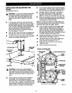
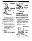
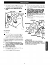
ALIGNING THE TABLE SQUARE TO THE
BLADE
See Figure 19.
_1_ WARNING: To prevent accidental starting that
could cause possible serious personal injury,
turn off the saw, remove the switch key, and
unplug the saw before making adjustments.
m:- - From the back of the saw, push the lock lever
counterclockwise or to the left 1/4 turn to unlock
the blade guide assembly. See Figure 11, page
13.
• Rotate the blade guide knob to move the blade
guide assembly all the way up. Return lock lever
to the upward position to lock assembly in place.
• Loosen table lock knob. See Figure 7, page 12.
Place a small combination square on table
beside blade.
ZEROSTOP
SETSCREW
BLADEGUIDE
ASSEMBLY
SMALL
SQUARE
Fig. 19
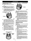
ADJUSTING THRUST BEARINGS, BLADE
GUIDE SUPPORT, AND BLADE GUIDES
See Figures 20, 21_ and22.
The upper and lower blade guides and tl_rustbearings
support the band saw blade during cutting operations.
The adjustment of the guides and bearings should be
checked whenever a different blade is installed.
WARNING: To prevent accidental starting that
could cause possible serious personal injury,
turn off the saw, remove the switch key, and
unplug the saw before making adjustments.
To Adjust Thrust •earings
• Adjust the thrust bearings first. Using the 1/8 in.
hex key, loosen the thrust bearing screw.
Note: The thrust b_aring screw is the upper cap
screw located on the right side of the blade guide
assembly. It is the lower cap screw on the right side of
the frame below the table for the lower bearing.
16