


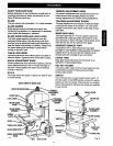
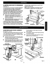
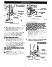

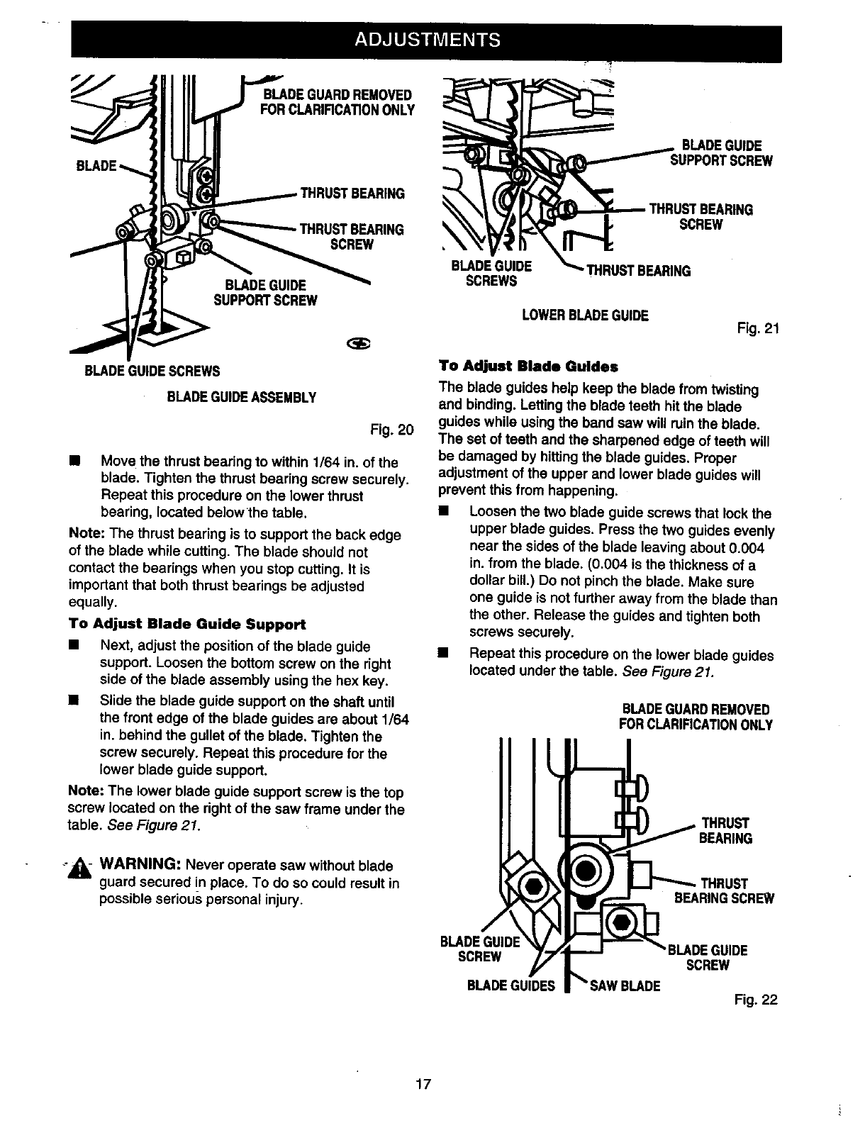
BLADE
BLADEGUARDREMOVED
FORCLARIRCATIONONLY
BLADEGUIDE
• THRUSTBEARING
SCREW
BLADEGUIDE
SUPPORTSCREW
BLADEGUIDESCREWS
BLADE GUIDEASSEMBLY
Fig. 20
• Move the thrust bearing to within 1/64 in. of the
blade. Tighten the thrust bearing screw securely.
Repeat this procedure on the lower thrust
bearing, located below the table.
Note: The thrust bearing is to support the back edge
of the blade while cutting. The blade should not
contact the bearings when you stop cutting. It is
important that both thrust bearings be adjusted
equally.
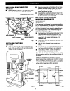
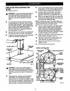
TO Adjust Blade Guide Support
• Next, adjust the position of the blade guide
support. Loosen the bottom screw on the right
side of the blade assembly using the hex key.
• Slide the blade guide support on the shaft until
the front edge of the blade guides are about 1/64
in. behind the gullet of the blade, Tighten the
screw securely. Repeat this procedure for the
lower blade guide support.
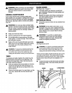
Note: The lower blade guide support screw is the top
screw located on the right of the saw frame under the
table. See Figure 21.
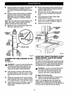
_,i_ WARNING: Never operate saw without blade
guard secured !n place. To do so could result in
possible serious personal injury.
SCREW
BLADEGUIDE
SCREWS
rHRUBTBEARING
LOWERBLADEGUIDE
Fig. 21
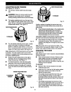
To Adjust Blade Guides
The blade guides help keep the blade from twisting
and binding. Letting the blade teeth hit the blade
guides while using the band saw will ruin the blade.
The set of teeth and the sharpened edge of teeth will
be damaged by hittingthe blade guides, Proper
adjustment of the upper and lower blade guides will
prevent this from happening.
• Loosen the two blade guide screws that lock the
upper blade guides. Press the two guides evenly
near the sides of the blade leaving about 0.004
in. from the blade. (0.004 is the thickness of a
dollar bill.) Do not pinch the blade. Make sure
one guide is not further away from the blade than
the other. Release the guides and tighten both
screws securely.
• Repeat this procedure on the lower blade guides
located under the table. See Figure 21.
BLADEGUARDREMOVED
FORCLARIRCATIONONLY
, THRUST
BEARING
BEARINGSCREW
BLADEGUIDE 3UIDE
SCREW SCREW
BLADEGUIDES
Fig. 22
17